OPERATIONS MANUAL MiniLink® Wireless Ethernet Systems MicroTek Electronics, Inc. 25691 Atlantic Ocean Drive, Suite B-3; Lake Forest, CA 92630 Information Hotline 888-36-MICRO www.microtekelectronics.
IMPORTANT SAFETY INSTRUCTION For your protection, please read and observe all safety instructions before operating this system and keep this sheet and any additional instructions for future reference. INSTALLATION & USE OBSERVE WARNINGS: All warnings in the operating instructions should be carefully followed. Do not make any modifications to the WEM, PIM, or any other MicroTek electronic device, as the unit will no longer comply with FCC regulations and therefore cancel its warranty.
FCC Output Power Restrictions The FCC does not require licensing to implement this device. License-free operation in the industrial, scientific, and medical band is documented in FCC Rules Part 15.247. It is the responsibility of the individuals designing and implementing the radio system to assure compliance with any pertinent FCC Rules and Regulations. This device must be professionally installed. Exposure to Radio Frequency Fields The Minilink 5.8WES is designed to operate at 5.
FCC REGULATORY ALERT Regulatory Alert As of July 20, 2007, a new FCC regulation has gone into effect which impacts operators of the U-NII band in the United States. As a result of this regulatory change, several MicroTek products are affected. The new FCC regulation impacts the sale of wireless equipment in the 5.25-5.35 GHz band. The regulation states that all devices imported and marketed after the July 20th, 2007 deadline must support radar detection as specified by the FCC in the 5.255.35 GHz band.
INDEX SECTION PAGE # IMPORTANT SAFETY INSTRUCTIONS, FCC NOTICE ---------------- ( i ) RADIO FREQUENCY EXPOSURE, INDUSTRY CANADA ------------- ( ii ) IMPORTANT FCC REGULATORY NOTICE------------------------------- ( iii ) QUICK START GUIDE ----------------------------------------------------------- 2 PRE-INSTALLATION REMINDER, RETURN POLICY ----------------- 3 WEM DESCRIPTION ------------------------------------------------------------- 4 FRONT, REAR & SIDE VIEWS --------------------------------------------
QUICK START PROCEDURES MicroTek Electronics, Inc. recommends that all equipment be bench tested before being installed onsite. This test will ensure the equipment is functioning properly. IMPORTANT: SEE NEW FCC REGULATORY ALERT ON PAGE “( iii )” WIRELESS ETHERNET MODULE SETUP 1. Remove the Host and Client from the box, select frequency via the rotary switch at the side of the unit.
PRE-INSTALLATION REMINDERS The information on the Quick Start Guide is intended for ease of use and application, the following reminders will help to ensure your satisfaction with MicroTek products and service. 1. Read through this manual before bench testing and installation 2. A helpful IP Address Locating tool is available to download from our website at http://www.microtekelectronics.com/softwaretools.htm. Download the Locator.exe tool. 3.
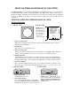
MINILINK WIRELESS ETHERNET SYSTEM (WES) The MiniLink WES is a plug and play CAT5/Ethernet cable replacement device. It operates in the 5.8 GHz U-NII bands on 5 non-overlapping channels. The WES system enables a wide variety of IP cameras, DVRs, encoders/decoders and web servers to be used across wireless line-of-sight links in ranges of 500 feet to 30 miles. The system operates independent of any network it may be connected to. MINILINK WIRELESS ETHERNET MODULE (WEM) WEM DESCRIPTION A. FRONT VIEW B.
POWER INJECTION MODULE (PIM) Note: The Power Injector Modules are not weatherproof units and must be protected from moisture. PIM DESCRIPTION A. TOP VIEW 2 1 3 1. ETHERNET IN – Connect to Ethernet device 2. POWER IN – 12-20 VDC Center Positive 3. ETHERNET OUT – Connect to Host/Client B. RIGHT SIDE VIEW 1. POWER LED – Lit when power is on 2. ETHERNET OUT – Connect to Host/Client 3. POWER IN – Connect to Power Supply 1 2 3 C. LEFT SIDE VIEW 1.
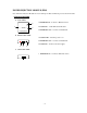
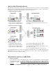
WES CONNECTION DIAGRAMS The following wiring schemes represent the configurations that have been tested and verified by MicroTek Electronics based on typical Ethernet wiring solutions. Other wiring configurations could be possible based on the application. A bench test is recommended to verify the designs below. A. POINT-TO-POINT SYSTEM ML ENC shown 1. Client Wireless Ethernet Module 2. Host Wireless Ethernet Module 3. Cat5 Connection to Ethernet Device 4.
WEM INSTALLATION & OPERATION (cont’d) B. MOUNT DIRECTIONAL HOST/CLIENT Mount the Host/Client with the Directional WEM included wall/pole mount B-1 bracket and hardware. Connect the black mounting assembly with adjustment swivel to mounting L-shaped bracket with the ¼ - 20 button head screw. Connect the unit to the mounting assembly using the ¼-20 mounting hole in the case. Position the Host and point it in the direction of the Client (or viceversa) and tighten the swivel mount.
WEM INSTALLATION & OPERATION (cont’d) E. CONNECT HOST/CLIENT Connect the cable to the Host/Client. Slide the cable jacket up to the base of the connector. Slide the weatherproof connector over the cable jacket and screw it into the Host/Client and tighten. Tighten the clamping nut until the CAT5 cable is sealed in the connector. Check the antenna positioning and make sure the Power and Link Activity LEDs are on.
B. MULTI-CONNECT SYSTEMS (cont’d) If you ordered a complete system with multiple Client SUs, they have been pre-configured with IP addresses as follows: ML WES Modules Unit 1 Unit 2 Unit 3 Unit 4 Unit 5 ML WES Serial Number 05618* 05619* 05620* 05621* 05622* ML WES IP Address Host AP, Client SU or Point to Point 192.168.1.200 192.168.1.201 192.168.1.202 192.168.1.203 192.168.1.
WEB PAGES (cont’d) B. STATUS – DEVICE STATUS 1. POINT-TO-POINT HOST AP The Device Status page provides the details of how the Single-Point Host is configured. The Access Point Name can be changed on the “Admin” page under the ADVANCED tab but the SSID cannot change. The updated firmware version is as shown: 7.06. One of the two jumper settings may be “on” depending on the range of the system.
B. STATUS – DEVICE STATUS (cont’d) 2. MULTI-CONNECT HOST AP The Device Status page provides the details of how the Multipoint Host is configured. 3. CLIENT SU The Device Status page provides the details of how the Client is configured.
WEB PAGES (cont’d) C. STATUS – HOST/CLIENT ASSOCIATION LISTS 1. POINT-TO-POINT AND MULTI-CONNECT HOST RSSI= Received Signal Strength Indicator. The Client List page of the Host AP shows the MAC address(s) of the paired or grouped Client SU(s) that are connected to the Host AP. For Point-to-Point systems, one MAC address will be shown. For Multi-connect systems, the Host AP will show all of the Client SU MAC addresses currently connected.
WEB PAGES (cont’d) D. STATUS – STATISTICS The Statistics page will indicate the number of transmitted and received data packets versus the number of dropped packets.
WEB PAGES (cont’d) E. BASIC - WIRELESS The wireless page is used for enabling Super mode. The Super mode combines adjacent channels to provide up to 50+ Mbps of throughput. The channels available in Super mode are: 4 and 6 only. If another channel is selected, Super mode will not be enabled. To enable Super mode, click the arrow in the drop down box and select “Super A without Turbo” (30+ Mbps) or “Super A with Static Turbo” (50+ Mbps).
F. BASIC – ETHERNET 1. NETWORK SETTINGS The Network Settings page is used for changing the IP Address, Subnet Mask and or Default Gateway of the Host or Client.
WEB PAGES (cont’d) G. ADVANCED – ADMINISTRATION This section of the Advanced tab is used for changing the password and other administration services for the Host or Client. H. ADVANCED – SYSTEM To reboot the system and/or bring it to its default settings, visit the system page of the Advanced tab.
WEB PAGES (cont’d) I. ADVANCED – FIRMWARE This page is used to flash firmware upgrades should it be necessary to do so.
SYSTEM INSTALLATION NOTES A. SYSTEM LOCATION 1. Address: _________________________________________________________ 2. Contact: _________________________________________________________ 3. Phone Number: ___________________________________________________ B.
WEM SPECIFICATIONS RF Modules RF SECTION Power Output Transmitting Frequency Channel Capacity Modulation Latency Sensitivity Polarization Antenna Type & Gain Beam Width Data Throughput Rate FCC ID Industry Canada MANAGEMENT Interface Frequency Selection Web Browser Interface Access Method Protocols Used MECHANICAL Physical Dimensions Weight POWER Power Requirements Power Method 50 W EIRP @ 5.8 GHz (maximum) 5.725 – 5.825 GHz (U-NII-3 / ISM) 5 non-overlapping channels 5.
WEM SPECIFICATIONS (cont’d) Power Injection Module MECHANICAL Physical Dimensions Weight Interface POWER Power Requirements Power-over-Ethernet (PoE) Plastic housing, not weatherproof 2.6” x 2.6” x 1.1” 2.5 oz 2 – RJ45 connectors Indicator Connectors 12 VDC 500 mA (wall transformer supplied) PoE “mid-span” compliant (pins 4,5 positive – pins 7,8 ground) LED - red DC Jack 2.5 mm x 5.
TROUBLE SHOOTING PROBLEM No Link Activity No Signal Level LED or Flashing Signal Level LED All three solid LEDs but no picture or picture drops out after a period of time No Green Signal Level LED (When using the ML WES-30 or ML WES-12) SUGGESTION 1. No power from connected device–make sure the connected Ethernet/IP device is powered. 2. Check all cables and connectors.
FAQ Q. Which unit is the transmitter and which is the receiver? A. WES systems are bi-directional so it is not critical which of the units is mounted at the receive location (and vice-versa). Typically, however, the ‘Host’ is located at the receive end and the ‘Client’ is at the transmit location. Q. How can I tell whether I received the point-to-point WES system versus the point-tomultipoint WES system? A. There are a few ways to tell which system you have: 1.
WARRANTY INFORMATION MicroTek Electronics extends the following LIMITED WARRANTY to the original owner/purchaser of this product as follows: - Two years from the date of initial sale for all wireless products. - One year from the date of initial sale for all encoder and decoder products.