OPERATIONS MANUAL MiniLink® Wireless Ethernet Systems MicroTek Electronics, Inc. 25691 Atlantic Ocean Drive, Suite B-3; Lake Forest, CA 92630 Information Hotline 888-36-MICRO www.microtekelectronics.
IMPORTANT SAFETY INSTRUCTION For your protection, please read and observe all safety instructions before operating this system and keep this sheet and any additional instructions for future reference. INSTALLATION & USE OBSERVE WARNINGS: All warnings in the operating instructions should be carefully followed. Do not make any modifications to the WEM, PIM, or any other MicroTek electronic device, as the unit will no longer comply with FCC regulations and therefore cancel its warranty.
FCC Output Power Restrictions The FCC does not require licensing to implement this device. License-free operation in the industrial, scientific, and medical band is documented in FCC Rules Part 15.247. It is the responsibility of the individuals designing and implementing the radio system to assure compliance with any pertinent FCC Rules and Regulations. This device must be professionally installed. Exposure to Radio Frequency Fields The Minilink 5.8WES is designed to operate at 5.
INDEX SECTION PAGE # IMPORTANT SAFETY INSTRUCTIONS, FCC NOTICE ---------------- ( i ) RADIO FREQUENCY EXPOSURE, INDUSTRY CANADA ------------- ( ii ) QUICK START GUIDE ----------------------------------------------------------- 2 PRE-INSTALLATION REMINDER, RETURN POLICY ----------------- 3 WEM DESCRIPTION ------------------------------------------------------------- 4 FRONT, REAR & SIDE VIEWS -------------------------------------------------- 4 - 5 PIM DESCRIPTION ------------------------------------------
QUICK START GUIDE MicroTek Electronics, Inc. recommends that all equipment be bench tested before being installed onsite. This test will ensure the equipment is functioning properly. WIRELESS ETHERNET MODULE (WEM) SETUP 1. Remove the WEMs from box, select frequency via the rotary switch at the side of the unit. (Factory set to channel 1 – channels 0, 1 & 2 are the same frequency) The channels of each set of WEMs must be matched for the WEMs to communicate with each other.
PRE-INSTALLATION REMINDERS The information on the Quick Start Guide is intended for ease of use and application, the following reminders will help to ensure your satisfaction with MicroTek products and service. 1. Read through this manual before bench testing and installation 2. Perform a bench test incorporating all components of the application 3. Install your MiniLink Wireless Ethernet System 4.
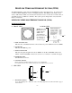
MINILINK WIRELESS ETHERNET SYSTEM (WES) The MiniLink WES is a plug and play CAT5/Ethernet cable replacement device. It operates in the 5.3 and 5.8 GHz U-NII bands on 8 non-overlapping channels. The WES system enables a wide variety of IP cameras, DVRs, encoders/decoders and web servers to be used across wireless line-ofsight links in ranges of 500 feet to 30 miles. The system operates independent of any network it may be connected to. MINILINK WIRELESS ETHERNET MODULE (WEM) WEM DESCRIPTION A.
C. SIDE VIEW (cont’d) 2. ETHERNET PORT Standard RJ-45 connector. 3. ROTARY CHANNEL SELECT SWITCH Shows switch settings for channels 0 – 9. *Note: Channels 0, 1 and 2 are the same frequency. If two or more systems are in use and either channel 0, 1 or 2 are used on the first system, the following systems must be set to channel 3 or higher. If the second system is not set to channel 3 or higher, the two systems could interfere with one another.
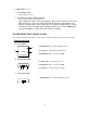
WES CONNECTION DIAGRAM The following wiring schemes represent the configurations that have been tested and verified by MicroTek Electronics based on typical Ethernet wiring solutions. Other wiring configurations could be possible based on the application. A bench test is recommended to verify the designs below. A. POINT-TO-POINT SYSTEM Transmit Location Receive Location HOST CLIENT PIM PIM Power Supply Power Supply Straight-through Ethernet Cable Straight-through Ethernet Cable B.
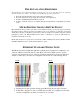
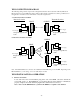
WEM INSTALLATION & OPERATION (cont’d) B. MOUNT DIRECTIONAL WEM Mount the WEM with the included wall/pole mount B-1 bracket and hardware. Connect the mounting block with ball adjustment to mounting bracket with the ¼ - 20 button head screw. Connect the WEM to the mounting block using the ¼-20 mounting holes in the WEM. Position the WEM and point it in the desired direction Tighten the jam nut against ¼ - 20 Button Head the bottom of the WEM case Screw - 1x to lock it in position.
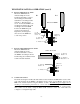
WEM INSTALLATION & OPERATION (cont’d) E. CONNECT WEM Connect the cable to the WEM. Slide the cable jacket up to the base of the connector. Slide the weatherproof connector over the cable jacket and screw it into the WEM and tighten. Tighten the clamping nut until the CAT5 cable is sealed in the connector. Check the WEM positioning and make sure the Power and Link Activity LEDs are on.
B. MULTI-CONNECT SYSTEMS (cont’d) Administration Page (Section E below) manually. If you ordered a complete system with multiple Client SU WEMs, they have been pre-configured with IP addresses as follows: Client SU WEM Unit 1 Unit 2 Unit 3 Unit 4 Unit 5 Serial Number 00511* 00512* 00553* 00624* 00714* IP Address 192.168.1.201 192.168.1.202 192.168.1.203 192.168.1.204 192.168.1.
WEB PAGES (cont’d) B. INFORMATION 1. POINT-TO-POINT HOST AP WEM The information page provides the details of how the Single-Point Host WEM is configured. Access Point Name: Bridge Name: MAC Address: Firmware Version: Current Channel: Turbo Mode: Rotary Switch Pos: 25.5dBi Jumper: 17.
A. INFORMATION (cont’d) 2. MULTI-CONNECT HOST AP WEM The information page provides the details of how the Multipoint Host WEM is configured. 3. CLIENT SU WEM The information page provides the details of how the Client WEM is configured.
WEB PAGES (cont’d) C. STATIONS/APs 1. POINT-TO-POINT AND MULTI-CONNECT HOST AP WEMS The Stations/Associations page of the Host AP WEM shows the MAC address(s) of the paired or grouped Client SU WEM(s) the Host AP WEM is connected to. For Point-to-Point systems, one WEM MAC address will be shown. For Multi-connect systems, the Host AP WEM will show all of the Client SU WEM MAC addresses currently connected.
WEB PAGES (cont’d) D. WIRELESS The wireless page is used for enabling Super mode. The Super mode combines adjacent channels to provide up to 50+ Mbps of throughput. The channels available in Super mode are: 3, 6 and 8 only. If another channel is selected, Super mode will not be enabled. To enable Super mode, click the arrow in the drop down box and select “Super A without Turbo” (30+ Mbps) or Super A with Static Turbo” (50 Mbps). Each WEM in your system will need to have this feature enabled independently.
D. SECURITY (cont’d) 2. WEP CONFIGURATION The security page is used for enabling WEP encryption and setting the parameters for WEP encryption. Click the “Enable WEP” check box to enable (The WPA configuration will be automatically disabled). After this box is checked, the Default WEP key is available, as are: Authentication, WEP key lengths and WEP Key 1-4. After updating the settings as desired, click save to update the WEM.
WEB PAGES (cont’d) F. ADMINISTRATION This section of the Administration page is used for rebooting the WEM, resetting the default configuration and/or upgrading/uploading the firmware in the system. Contact MicroTek to obtain the files for a firmware upgrade. The latest firmware is 6.04P (7.01). Once the file(s) is/are received, save it/them a file to be easily accessed in your computer and click “Browse” to search for the file to upload.
E. ADMINISTRATION (cont’d) This section of the Administration page is used for selecting the device name, changing IP settings and changing the user name and password needed to access the system. NOTE: The Device name on the Admin page of a HOST AP will be “MicroTek Host AP”. The Device name on the Admin page of a Client SU will be “MicroTek Client”. For Point-to-Point systems default IP addresses will be as follows: Host AP: 192.168.1.200 Client SU: 192.168.1.
SYSTEM INSTALLATION NOTES A. SYSTEM LOCATION 1. Address: _________________________________________________________ 2. Contact: _________________________________________________________ 3. Phone Number: ___________________________________________________ B.
WEM SPECIFICATIONS RF Modules RF SECTION Power Output Transmitting Frequency Channel Capacity Modulation Latency Sensitivity Polarization Antenna Type & Gain Beam Width Data Throughput Rate FCC ID Industry Canada MANAGEMENT Interface Frequency Selection Web Browser Interface Access Method Protocols Used MECHANICAL Physical Dimensions Weight POWER Power Requirements Power Method 1 W EIRP @ 5.3 GHz (maximum) 50 W EIRP @ 5.8 GHz (maximum) 5.250 – 5.350 GHz (U-NII-2) 5.725 – 5.
WEM SPECIFICATIONS (cont’d) Power Injection Module MECHANICAL Physical Dimensions Weight Interface POWER Power Requirements Power-over-Ethernet (PoE) Plastic housing, not weatherproof 2.6” x 2.6” x 1.1” 2.5 oz 2 – RJ45 connectors Indicator Connectors 12 VDC 500 mA (wall transformer supplied) PoE “mid-span” compliant (pins 4,5 positive – pins 7,8 ground) LED - red DC Jack 2.5 mm x 5.
TROUBLE SHOOTING PROBLEM No Link Activity No Signal Level LED or Flashing Signal Level LED All three solid LEDs but no picture or picture drops out after a period of time No Green Signal Level LED (When Using the MLWES-30 with two 18” Parabolic Dishes) SUGGESTION 1. NO POWER – make certain both WEMs have power and the red Power LED is on. Make sure the connected Ethernet/IP device is powered. 2. Check the configuration of all WEMs.
FAQ Q. Which unit is the transmitter and which is the receiver? A. WES systems are bi-directional so it is not crucial which of the units is mounted at the receive location (and vice-versa), however, typically the ‘host’ is the receiver and the ‘client’ is the transmitter. Q. How can I tell whether I received the point-to-point WES system versus the point-tomultipoint WES system? A. There are a few ways to tell which system you have: 1.
WARRANTY INFORMATION MICROTEK LIMITED WARRANTY MicroTek Electronics extends the following LIMITED WARRANTY to the original owner/purchaser of this product: 1) If, within two years after date of initial sale, this product, or any part or portion thereof, shall prove upon examination by MICROTEK, to be defective in material or workmanship, MICROTEK will repair or replace such part or portion at MICROTEK’s option.