English Copyright © 2000 Microtek International Inc. All rights reserved. June 2000 I49-002799B Trademarks Important Microtek™, Artix™, ScanWizard Pro™, and ArtixScan™ are trademarks of Microtek International Inc. Windows® is a registered trademark of Microsoft Corporation. Other product or company names are trademarks of registered trademarks of their respective holders. Documents you scan may be protected under copyright law.
1 Introduction ............................................................................................................................ 1 2 General Installation .............................................................................................................. 4 1. 2. 3. 4. Unpacking the Scanner ................................................................................................... 4 Unlocking the Carriage ..........................................................................
English 2. Positioning transparent film ........................................................................................... 19 A. B. C. D. E. Using the Universal Glass Film Holder ........................................................................................... 20 Using the 35mm Slide Holder .......................................................................................................... 21 Using the 35mm Filmstrip Holder .........................................................
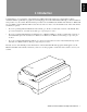
English 1 Introduction Congratulations on your purchase of the ArtixScan™ 2500 scanner! The single-pass, 36-bit, high-resolution ArtixScan 2500 is specifically for graphic arts and imaging professionals. This manual will help you in the installation and operation of your scanner. The information provided covers both Macintosh and PC environments for Windows® 95 / 98 / 2000, as well as Windows NT 4.0. See the notes below on how to use the manual, based on the environment in which you operate.
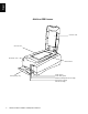
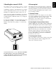
English ArtixScan 2500 Scanner Scanner cover Vertical ruler Horizontal ruler Glass surface Transparency tray 2 ArtixScan 2500 Installation and Operation Manual Power switch Power LED (green) Reflective Ready indicator (orange) Transparency Ready indicator (orange)
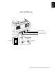
English ArtixScan 2500 Scanner Power connector SCSI 25-pin connector SCSI 50-pin connector ON ID switch 6 OFF Terminator switch + ArtixScan 2500 Installation and Operation Manual 3
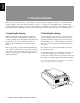
English 2 General Installation This section provides information on procedures you need to perform or things to check on your ArtixScan 2500 scanner regardless of the environment in which you operate — whether it is on the Macintosh or on the PC. The general installation procedures cover the following subjects: 1) unpacking your scanner; 2) unlocking the scanner; 3) resetting the scanner’s SCSI ID if necessary; 4) powering up the scanner; and 5) choosing your scanning station. 1. Unpacking the Scanner 2.
4. Power-up test Note: This procedure is provided as a reference, you may or may not need to change the SCSI ID on your scanner. All scanners are factory tested, however, to ensure that your scanner has not been damaged during shipment, the following preliminary power-up test must be performed. Contact your dealer immediately if the scanner is not in proper working condition. A SCSI ID is assigned to each SCSI device in your daisy chain to differentiate the devices from one another.
English D. Observing the Scanner Boot Process The following sequence of events should take place after power up: • • • The scanner performs a self-test by homing the carriages and camera box. Through the platen glass, you will be able to observe the carriage moving, and you will hear a series of clicking noises associated with the operation of the scanner motors. These “clicking” noises are normal.
English 3 Installation on the Macintosh This section provides information on installing the ArtixScan 2500 on the Macintosh. The procedures are divided into two main sections: 1) Installation for Macintosh computers that feature built-in SCSI ports; and 2) Installation for Macintosh G3 or G4 computers without SCSI ports/cards. For these computers, you will be installing the SCSI interface card included with your scanner package. A. Installation for Macintosh computers that feature built-in SCSI ports 1.
English B. Installation for Macintosh G3 or G4 computers (without SCSI ports/cards) 1. Installing the interface card 2. Connecting the scanner Before installing the interface card, make sure you turn off your computer and peripherals. Then follow the steps below: 1. Shut down your computer. 2. Connect the scanner to your computer, using the SCSI cable provided in the scanner package. 1. Shut down your computer and unplug the power cord. Next, open your computer. 2.
C. Installing the software If you are connecting the scanner in a daisy chain to other SCSI devices (such as a CD-ROM drive), take note of the following: Install all the software on your ScanWizard Pro™ CD-ROM, which contains the ScanWizard Pro scanning software, ICC profiles and the Microtek Scanner Profiler™ software for calibrating the ArtixScan 2500 (see page 25). A.
English 4 Installation on Windows 95 / 98 / 2000 1. Installing the interface card 2. Checking the interface card status 1. Turn off your PC and peripherals, and unplug the power cord. Next, remove the cover from your computer. When Windows starts with the new Adaptec SCSI card installed in your computer, the card is detected and the driver is automatically installed. You may be asked to insert your Windows CD-ROM. Do so, and follow the steps below to check your card status. 2.
English 3. Installing the software 4. Connecting the scanner Install all the software on your ScanWizard Pro CDROM, which contains the ScanWizard Pro scanning software, ICC profiles and the Microtek Scanner Profiler™ software for calibrating the ArtixScan 2500 (see page 25). 1. Turn off your PC. 2. Plug the 25-pin end of the SCSI cable into the Adaptec card at the back of the computer. Then plug the 50-pin end of the SCSI cable into the back of the scanner.
English 5. Termination 6. Troubleshooting If you are connecting the scanner in a daisy chain to other SCSI devices (such as a CD-ROM drive), take note of the following: After installing the interface card in your computer and connecting the scanner, you may find yourself unable to use the scanner. This is usually due to any of the situations described below: 1. If the scanner is the last device on the SCSI chain, set the internal terminator switch on the back of the scanner to the “ON” position.
English 6. To resolve the conflict, uncheck “Use automatic settings”, then click to modify the individual resource, one after another, until the message “No conflicts” appears in the Conflicting device list. For example, to resolve the Memory Range conflict, take these steps: a) At the Resource type, double-click on the Memory Range string, the Edit Memory Range dialog box is displayed.
English 7. When you get a “No conflicts” message in the Conflicting device list, the Memory Range conflict is resolved. Take similar steps for the Interrupt Request (IRQ) and Input/Output Range resources. If all of IRQs are taken, you need to contact your computer dealer for help on how to free up an IRQ resource. Resolving situation C 1. Click Start, Settings, and select Control Panel. 2. Double-click Add New Hardware. 3.
English 7. When installation is complete, Windows will ask if you wish to shut down your computer. Select No. 8. Click Start, Settings, and select Control Panel. 9. Double-click on the System icon in Control Panel and select Device Manager from the top. 10. Double-click on “SCSI controllers” to check whether conflict happens. If a conflict exists, follow the steps in Resolving Situation B. 11. When the settings are all correct, click OK to save the modifications.
English 5 Installation under Windows NT 4.0 1. Installing the interface card 4. Connecting the scanner See page 11 for details. Connecting the scanner on Windows NT 4.0 is the same as that under Windows 95 / 98 / 2000. See page 10 for details. Card installation on Windows NT 4.0 is the same as that under Windows 95 / 98 / 2000. 2. Installing the Windows NT driver 5.
English 3. In the Control Panel window, find SCSI Adapters and double click it. A window like the following below will appear. Adaptec SCSI driver is not listed here 6. Restart your computer. The Devices screen will list any SCSI controllers that may already have been installed in your computer. Note: IDE CD-ROM drives are not SCSI, but Windows NT 4.0 will still list it on the screen because of the way the driver is implemented 4.
English 6 Operating the Scanner This section provides information on how to operate the ArtixScan 2500. The subjects covered in this section include how to position your images for scanning and how to use the various holders included in your scanner package when scanning transparent film. 1. Positioning reflective materials This procedure applies when you use the upper scan bed of the ArtixScan 2500. The upper scan bed is used for scanning reflective materials such as photos and prints. A.
This procedure applies when you use the lower scan bed of the ArtixScan 2500, which has a transparency tray that is used for scanning transparent film. There are two ways to scan transparent film: 1) By using the Universal Glass Holder with the transparency tray; or 2) By using the other film holders with the transparency tray, also included in your scanner package. See below for more details.
2. Place the vinyl strip on the edge of the transparency to secure the transparency. 3. Pull the transparency tray out slightly, then place the Universal Glass Film Holder into the transparency tray. Make sure the holder is seated firmly in the transparency tray. 4. Gently push the transparency tray back in. R To scan non-standard-sized transparent film, place the film face down on top of the glass surface of the Universal Glass Film Holder. R 1.
2. Pull the transparency tray out slightly, then place the 35mm slide holder into the transparency tray. Make sure the holder is seated firmly in the transparency tray by pushing down on each corner of the holder firmly. 3. Gently push the transparency tray back in. 1. Insert the individual 35mm slides to be scanned into the 35mm Slide Holder. Scanning in high resolution: Insert the slides to be scanned into the holder in the area labeled “HIGH RESOLUTION”. High-resolution scanning is at 2,500 dpi.
English C. Using the 35mm Filmstrip Holder Scanning in high resolution: Insert the 35mm filmstrip into the holder in the area labeled “HIGH RESOLUTION” on the holder. High-resolution scanning is at 2,500 dpi. 1. Insert the 35mm filmstrip to be scanned into the 35mm Filmstrip Holder. a) Push to open the 35mm filmstrip holder. 2. Pull the transparency tray out a little, then place the 35mm filmstrip holder into the transparency tray.
English D. Using the 6 x 9 cm Film Holder Scanning in high resolution: Insert the film to be scanned into the holder in the area labeled “HIGH RESOLUTION”. High-resolution scanning is at 2,500 dpi. Insert the film to be scanned into the 6 x 9 cm Film Holder. a) Push on the side to open the holder. 2. Pull the transparency out a little, then place the 6 x 9 cm Film Holder into the transparency tray.
English E. Using the 4" x 5" Film Holder Scanning in high resolution: Insert the film to be scanned into the holder in the area labeled “HIGH RESOLUTION” on the holder. High-resolution scanning is at 2,500 dpi. 1. Insert the film to be scanned into the 4" x 5" Film Holder. a) Push on the side to open the holder. 2. Pull the transparency tray out a little, then place the 4" x 5" Film Holder into the transparency tray.
English 7 Using the Scanner ICC Profiler Program 1. Introduction 2. Calibration targets The Scanner ICC Profiler is a scanner calibration and profiling utility program designed exclusively for use with Microtek scanners, including the ArtixScan 2500. The Scanner ICC Profiler lets you calibrate the color attributes of your scanner and lets you create an ICC color profile customized and tailored especially for your scanner.
English 4. Installing the Scanner ICC Profiler 5. Placing the color target Note: The Scanner ICC Profiler program should have been installed at the time you performed software installation procedures (discussed earlier in the manual). If for some reason you have not installed the Scanner ICC Profiler, follow the steps below to install the program.
English Additional Notes: Proper positioning of the reflective target The correct positioning of the reflective color target on the ArtixScan 2500 is critical. The lens of the scanner is only 4 inches wide, and unless the target is positioned exactly as shown below, the scanner may miss out on scanning the calibration area of the 5"x7" target. A slight deviation from the correct positioning, for example, may mislead the scanner into reading the non-calibration area instead. 2.
English 6. Calibration Note: ICC Profiler utility performs identical function to both the Windows and Macintosh versions, though the screen appears slightly different. In this section, the Windows version is used for step-by-step instructions. 1.
Scan frame encloses target image To resize the selection, move the cursor to any corner of the frame; the pointer is changed to a double-headed arrow. Hold down the mouse, drag to form a new selection, then release the mouse. When the target image is selected, click the Scan button to scan the target. B.
English 9. Creating a profile Exit the Scanner ICC Profiler now, and use the new scanner profile with ScanWizard Pro to scan excellent color images. Following the alignment of registration marks, an instruction dialog box appears, prompting you to click the Calibrate Profile button. Click the Calibrate Profile button. This only takes a few moments. When the process is finished, a Save Profile As dialog box appears, prompting you to input Profile Filename and Profile Description.
in which the tonal reproduction curve of the profile is controlled. This section describes the features and commands of the Microtek Scanner ICC Profiler program. All features are covered in the Main window and Calibration window. • Normal: Slightly brightens the highlights but also darkens the shadows. A. The Main Window • Lighten: Brightens the highlights and also lightens the image overall. The Main window provides various features and a system menu, allowing you to control the calibration process.
English To use this command: B. System Menu The System Menu displays current scanner information, lets you view the SCSI chain status, and lets you view the About dialog box of the Scanner ICC Profiler program. a) Choose the Get SCSI Chain Info command. b) If your scanner does not show in the list, make sure it is connected and turned on, then click on the Probe button in the dialog box. • Choose the correct interface card in the card selection box.
1. Preview: The Preview button performs a preliminary scan of the target, displaying the entire target image in the calibration window. 2. Scan: The Scan button scans the target image and prepares the scanner for the important succeeding steps of aligning the registration marks and creation of the profile. D. The Calibration Window: Aligning targets and creating the profile 1.
English 11. Reference section for Macintosh This section describes the features and commands of the Microtek Scanner ICC Profiler program. All features are covered in the Menu commands, the Main window, and the Calibration window. A. Menu commands 1. Apple Menu — About ICC Profiler: Choose the About ICC Profiler command from your Apple menu to display the splash screen for the Scanner ICC Profiler program. The screen includes the product logo and the software version number. 2.
The Main window provides various features and a system menu, allowing you to control the calibration process. 4. Tonal Mapping: This option lets you select the way in which the tonal reproduction curve of the profile is controlled. • Normal: Slightly brightens the highlights but also darkens the shadows. • Lighten: Brightens the highlights and also lightens the image overall. • Darken: Darkens the shadows without changing the highlights. • Reduce Contrast: Captures as much of the original as possible.
English C. The Calibration Window: Preview and Scan 1. Preview: The Preview button performs a preliminary scan of the target, displaying the entire target image in the calibration window. D. The Calibration Window: Aligning targets and creating the profile 1. Create Profile: This button starts the actual calibration process in which a custom scanner ICC profile is created for the scanner.