FCC Compliance Statement This device complies with part 15 of the FCC Rules. Operation is subject to the following two conditions: 1. 2. This device may not cause harmful interference, and This device must accept any interference received, including interference that may cause undesired operation. FCC WARNING This equipment has been tested and found to comply with the limits for a Class B digital device, pursuant to Part 15 of the FCC Rules.
CE mark for Class B ITE (Following European standard EN55022/1998; EN61000-3-2/1995; EN61000-3-3/1995, EN55024/1998, EN60950/1992+A1+A2+A3+A4+A11) Radio Frequency Interference Statement Warning: This is a Class B product. In a domestic environment, this product may cause radio interference in which case the user may be required to take adequate measures.
TABLE OF CONTENTS Your New LCD Monitor Unpacking Identifying Components Hot Keys for Quick Adjusting of Monitor Settings Viewing Angle and Free Height adjusting Connecting the Power Connecting the Video Connecting the Stereo Speakers Power Management System The LCD Monitor’s Display Controls Adjusting the Monitor’s Display Appendix A: LCD Monitor Specifications Appendix B: Supported Timing Appendix C: Troubleshooting Procedures iii 1 1 2 4 6 7 8 9 9 10 10 17 19 20
The LCD Monitor Your New LCD Monitor Your LCD Monitor has been designed to be versatile, ergonomic and user-friendly. The LCD Monitor is capable of displaying most standards, from 640 x 400 VGA to 1280 x 1024 SXGA. The digital controls located on the front panel allows the user to easily adjust the Monitor’s display parameters, and the LCD Monitor’s small footprint allows you more room in your workspace for other peripherals.
Note: Using a computer for an extended period of time with a poor workstation set-up and incorrect working habits can cause health problems. The science of ergonomics studies the relationship between health and a suitable working environment. There is a section on ergonomics at the end of this chapter. For more information on ergonomics, contact your nearest computer bookstore, or local library. The Internet also has information on this and other subjects.
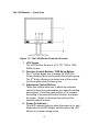
The LCD Monitor — Front View Figure 1-1: The LCD Monitor Panel and Controls 1. LCD Screen The LCD Monitor Screen is a 19” TFT 1280 x 1024 SXGA screen. 2. Function Control Buttons / OSD Menu Button The 1st button allows you to display the OSD (OnScreen Display) Menu and to select the function group. The 2nd button allows you to select one of the control functions within each function group. 3.
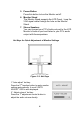
5. Power Button Press this button to turn the Monitor on/off. 6. Monitor Stand The Monitor Stand supports the LCD Panel. Loop the VGA signal cable through the hole on the Monitor Stand. 7. Stereo Speakers You can connect your PC’s Audio-out port to the LCD Monitor’s Audio-in port and listen to your PC’s audio output with these speakers. Hot Keys for Quick Adjustment of Monitor Settings Figure 1-2: Hot Keys 1.”Auto-adjust” hot key: nd Press the 2 function button to apply monitor settings automatically.
3.” Contrast-adjust” hot key: nd Press the 2 adjustment control button to adjust the contrast of the display directly. ** To close the OSD windows, press the power button once. The LCD Monitor — Rear View Figure 1-3: LCD Monitor’s Rear Ports 1. DC Power Jack for adapter Connect the AC adapter cable to this jack. 2. Audio Line-in Connect your PC’s line-out to this jack to listen the PC’s audio on the LCD monitor’s stereo speakers. (You can also connect your CD-ROM’s line-out to this jack.) 3.
Viewing Angle and Free Height Adjusting 6
Connecting the Power Please refer to the following instructions for connecting the power to the LCD Monitor. 1. Plug the female end of the power cable into the AC adapter and Plug the male end of the power cord into a wall socket. The plug on the power cable will vary according to the electrical standard in your area. Please refer to Figure 1-4. Figure 1-4: The AC Adapter 2. Connect the power connector of the adapter into the power jack of the LCD Monitor.
Connecting the Video 1. Turn off your PC and LCD Monitor. 2. Connect one end of the VGA signal cable to the PC’s D-sub VGA port and the other end to the monitor's VGA port. Please refer to Figure 1-6. 3. If your PC has a graphic card with a 24-pin DVI connector, you should connect it to the Digital 24-pin DVI signal cable. Figure 1-6: Connecting the LCD Monitor to the PC 4. Make sure the signal cable heads are securely connected to the VGA port (or DVI port) of your PC and Monitor.
Connecting the Stereo Speakers Please refer to the following instructions for connecting the LCD Monitor’s stereo speakers. 1. Connect the sound cable to the line-out of your PC’s audio card. 2. Connect the other end of the sound cable to the LCD Monitor’s line-in jack. Please refer to Figure 1-7. Figure 1-7: Connecting the Stereo Speakers 3. You can adjust the sound volume of the stereo speakers by using the speaker volume control function on the OSD (On-Screen Display).
The Display Controls The LCD Monitor’s Display Controls This chapter covers the LCD Monitor’s On-Screen Display (OSD). Using the OSD, you can adjust the contrast, brightness, display position, display clarity, color temperature, and speaker volume, as well as set OSD parameters. Please read this chapter carefully to get the most out of your LCD Monitor.
OSD Main Menu Function Control button to access the OSD main menu, press the OSD Menu button (the first Function button on your LCD Monitor). To scroll between the OSD main menu options, use the second Function Control button on your LCD Monitor. The highlighted option is the one that is currently selected. Analog or digital mode is automatically detected by the Monitor. A. Analog Mode Each main menu and submenu item is covered below.
PHASE: Use this option to adjust the focus and clarity of the display. CLOCK: Use this option to adjust the display pixel number alignment. RESET: Use this option to reset the H- Position, VPosition, Phase and Clock parameters. PORT-SELECT: Use this option to change input between the VGA port and DVI digital port. EXIT: Use this option to exit the Monitor Control submenu. OSD Control Option The OSD Control option lets you adjust the position of the OSD on the screen.
COLOR: Use this option to select the LCD monitor’s color display. The available options are 9300, 6500 and User. The 9300 and 6500 options let you set the Color Temperature to CIE coordinates 9300° or 6500°, respectively. Selecting the user option lets you make individual adjustments to the R, G and B items. R, G and B: Use this option to make individual adjustments to the Red / Blue / Green (RGB) gain for the color temperature.
B. Digital Mode Pressing the OSD Menu button causes the following screen to appear (an example): Main menu Submenu Description Figure 2-2: The OSD Main Menu The Monitor Control Option The Monitor Control option allows you to adjust the LCD monitor’s display characteristics. PORT-SELECT: Use this option to change input between the Monitor's VGA port and the DVI digital port. EXIT: Use this option to exit the Monitor Control submenu.
Graphic Control Option The Graphic Control option lets you make adjustments that affect the contrast, brightness and color of the LCD monitor’s display. CONTRAST: Use this option to adjust the difference between the lightest and darkest areas of the LCD monitor’s display screen. BRIGHTNESS: Use this option to adjust the light level on the LCD monitor’s display screen. The Brightness level should be adjusted in conjunction with the Contrast item.
Messages: 1. NO VIDEO When the monitor is ON and no Video signal is being received, the “NO VIDEO” message will be displayed. 2. Signal out of monitor’s supported range When the frequency range is out of the monitor’s specifications, or when the incoming resolution is higher than 1280x1024, the video data will be turned off and a warning message “OVER RANGE” will be displayed.
Appendix A LCD Monitor Specifications LCD Panel 19” SXGA Control Functions Power On-Screen Display (OSD) Software Power switch with LED indicator Main Menu Submenu Monitor Control Auto Adjust / Horizontal Position / Vertical Position / Phase / Clock / Reset / Graph./Text / Port Select / Exit OSD Control OSD Horizontal Position / OSD Vertical Position / OSD Timer / Exit Graphic Control Contrast / Brightness / Color / R / G / B / Auto Level / Reset / Exit Misc.
Input Detection AUTO-detection and OSD item for manual selection Scanning Frequency H/V, Hz (Analog mode) 24-80k 50-75 Scanning Frequency H/V, Hz (Digital mode) 30-80k 50-75 Power Management Meets VESA DPMS Power Consumption (ON/OFF, W) ON :46W max. OFF:5W max. Dimensions WxHxD mm 430 x 542 x 240 mm Net Weight (Approx.) 7.9 ± 1 Kg (17.4 Ibs) Power Supply Environment (Measured from AC inlet) 17” x 21” x 9.4” 12V/4.
Appendix B Supported Timing Item Standards Resolution Dot Clock (MHz) Vertical Scanning Frequency (Hz) Horizontal Scanning Frequency (kHz) Sync Polarity or composite sync (H/V) Operating Mode A/D/G 1 NEC PC98 640x400 25.20 70.15 31.50 -/- 2 NEC PC98 640x400 21.05 56.42 24.83 -/- A/G 3 MAC 13” mode 640x480 30.24 66.67 35.00 -/- A/D/G 4 MAC 16” mode 832x624 57.28 74.55 49.73 -/- A/D/G 5 MAC 17” mode 1024x768 80.00 75.02 60.24 -/- A/D/G 6 VGA 640x350 25.
Appendix C Troubleshooting Procedures This LCD Monitor was pre-adjusted in the factory with standard VGA timing. Due to output timing differences among various VGA cards, you may initially experience an unstable or unclear display when a new display mode or new VGA card is selected. This LCD Monitor Supports multiple VGA Modes. Refer to Appendix B for a listing of factory preset modes supported by this LCD Monitor.
press the bottom (or top) Adjustment Control button until the lines disappear and you have a clear display. PROBLEM: There is no LCD Display If there is no display on the LCD, please perform the following steps: 1. Make sure that the power indicator on the LCD Monitor is lit, all connections are secure, and the system is running on the correct timing. Refer to the Appendix B for information on timing. 2. Turn off the LCD Monitor and then turn it back on again.