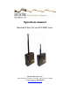
Operations manual MiniLink® Data 900 and 2400 MHz Series MicroTek Electronics, Inc. 25691 Atlantic Ocean Drive, Suite B-3; Lake Forest, CA 92630 Technical Support: 888-366-4276 www.microtekelectronics.
FCC NOTICE This equipment has been tested and found to comply with the limits of a Class B device, pursuant to PART 15 of the FCC Rules. These limits are designed to provide reasonable protection against harmful interference. This equipment generates, uses and can radiate radio frequency energy, and, if not installed and used in accordance with the instructions, may cause harmful interference to radio communications.
INDEX SECTION PAGE # FCC NOTICE ----------------------------------------------------------------- ( i ) INDUSTRY CANADA NOTICE ----------------------------------------- ( i ) QUICK START GUIDE ---------------------------------------------------- 2 PRE-INSTALLATION REMINDER, RETURN POLICY --------- 3 TRANSCEIVER DESCRIPTION---------------------------------------- 4 FRONT VIEW ---------------------------------------------------------------4 SIDE VIEW -----------------------------------------------------------
QUICK START GUIDE MicroTek Electronics, Inc. recommends that all equipment be bench tested before being installed onsite. This test will ensure that all components of your application are functioning properly. DATA TRANSCEIVER SET-UP 1. Remove each Transceiver from the box and attach its omni-directional dipole antenna. 2. If the device in use operates at a different Baud Rate than the factory setting of 4800, the radio must be changed to the desired Baud rate using the Software.
PRE-INSTALLATION REMINDERS The information on the Quick Start Guide is intended for ease of use and application, the following reminders will help to ensure your satisfaction with MicroTek products and service. 1. Read through this manual before bench testing and installation 2. Make sure that you set the Data radios to the Baud Rate that will match your Control and/or Camera 3. Perform a bench test incorporating all components of the application 4. Install your MiniLink Data 900 or 2400 MHz System 5.
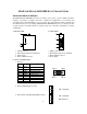
MINILINK 900 AND 2400 MHZ DATA TRANSCEIVERS TRANSCEIVER DESCRIPTION The MiniLink Data 900/2400 transceivers are either point-to-point or point-to-multi-point units. Software is provided to configure each radio to match the configurations of your camera and controlling device. If the Baud Rate is not set correctly, the control functions will not transmit and the camera will not move accordingly.
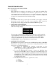
TRANSCEIVER OPERATION HOW TO SET UP EACH TRANSCEIVER 1. LOCATION Each Transceiver is designed to be placed on a flat surface for stability. The transceivers are not weatherproof and should be placed indoors or in an environmental enclosure if used outdoors or in a harsh environment. Included in each of MicroTek’s environmental enclosure is a piece of double-sided tape that can be used to mount the transceiver inside the housing. 2.
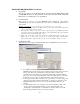
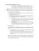
TRANSCEIVER OPERATION (Continued) 1. Set-up Tab This screen is used to set the PC Serial Port to interface with the MiniLink Data 900 or 2400 MHz Transceiver. The parameters in this tab must match the PC Serial Port Parameters for communication to be established. 2. Com Test Tab This screen is used to test the MiniLink Data transceiver and monitor communications once the two transceivers are both set to match the parameters of your system.
TRANSCEIVER OPERATION (Continued) • Avoid clicking on “Restore Module Defaults” as Multiple Default-Resets could result in a software lockout, requiring a factory reset of the Transceiver unit(s). If you are experiencing software difficulty, try refreshing by clicking on a separate file tab such as “Set-up” and re-click “Configuration” then try the command again. NOTE: All transceivers communicating with one another in a system must be configured identically.
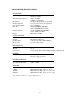
TRANSCEIVER SPECIFICATIONS RF SECTION Power Output Transmitting Frequency Modulation Channel Capacity Over Air Baud Rate FCC ID Industry Canada Europe 140 mW (900 MHz), 50 mW (2.4 GHz) 900 to 928 MHz 2.4000 to 2.4835 GHz Frequency Hopping Spread Spectrum 7 hop sequences share 25 frequencies Up to 19200 bps OUR9XSTREAM (900 MHz) OUR-24XSTREAM (2.4 GHz) 4214A-9XSTREAM (900 MHz) 4214A 12008 (2.4 GHz) ETSI, CE (2.
TROUBLESHOOTING PROBLEM Camera does not respond when PTZ control functions are moved Unit fails when Com Test is run There is a slight “blip” or other type of interference on the screen only when the PTZ control functions are accessed. SUGGESTION No wireless control should be the only problem that would be related to the MiniLink Data transceivers. For all other problems, refer to the operations manual for other equipment that is being used. Try the following suggestions to obtain wireless control: 1.
WARRANTY INFORMATION MICROTEK LIMITED WARRANTY MicroTek Electronics extends the following LIMITED WARRANTY to the original owner/purchaser of this product: 1) If, within two years after date of initial sale, this product, or any part or portion thereof, shall prove upon examination by MICROTEK, to be defective in material or workmanship, MICROTEK will repair or replace such part or portion at MICROTEK’s option.