
User Guide

3
Altering XYZ axis
NOTE: We only recommend altering the XYZ axis for complex sites
where you need less activation from a particular direction,
such as the exit road being close proximity to an entry road. In
this instance we would reduce the X field direction so that
a passing vehicle in next lane will not trigger the e-Loop.
Z = Vertical detection
Y = Approach and Depart detection (Arrow indication)
X = Left and Right-hand side detection
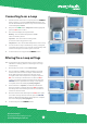
1. First make a connection to the e-Loop, then go to
MENU and
select Alter Settings and press
SET. Now scroll to the Axis you
want to change, then press
SET again.
2. If we are changing the X axis, you can set a value between
0% to 200% – this is the same for all X, Y and Z axis.
3. Use the Up or Down arrow buttons to change the value,
then press the SET button to confirm.
NOTE: All values should add up to a minimum of 300, so if reducing
one axis then another should be increased to compensate.
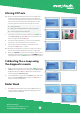
4. Now press
UPLOAD to confirm the new settings and the screen
will display Sending Settings. Then press the
CONNECT button to
disconnect the e-Loop, or
MENU button to access other options.
Calibrating the e-Loop using
the diagnostic remote
1. Make a connection to the e-Loop, then press MENU and select
Calibrate. The Calibrate menu screen will have Calibrate Loop
highlighted. Now press
SET to calibrate the e-Loop and the
screen will display Calibrating Loop.
2. To uncalibrate the e-Loop enter the Calibrate menu and scroll
down to select Uncalibrate Loop. Now press the
SET button,
and the e-Loop is uncalibrated.
Microtech Designs
enquiries@microtechdesigns.com.au
microtechdesigns.com.au
4
1
2 3
1
2
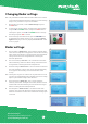
Radar Read
1. Press SET to read the radar sensor state. If False is shown it
means no object is detected. If True is displayed this means
an object has been detected.
1