
Int'l. Co. Ltd. Computer Hardware User Manual


MS-7563 Mainboard
2-18
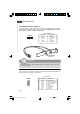
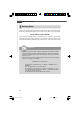
Front USB Connector: JUSB1 ~ 2
These connectors, compliant with Intel
®
I/O Connectivity Design Guide, is ideal for
connecting high-speed USB interface peripherals such as USB HDD, digital cameras,
MP3 players, printers, modems and the like.
1
2
9
10
JUSB1~2
PIN SIGNAL PIN SIGNAL
1 VCC 2 VCC
3 USB0- 4 USB1-
5 USB0+ 6 USB1+
7 GND 8 GND
9 Key (no pin) 10 USBOC
Pin Definition
Important
Note that the pins of VCC and GND must be connected correctly to avoid
possible damage.
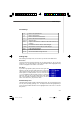
USB 2.0 Bracket
(Optional)
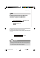
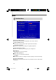
Serial Port Connector: JCOM 1
This connector is a 16550A high speed communication port that sends/receives 16
bytes FIFOs. You can attach a serial device.
PIN SIGNAL DESCRIPTION
1 DCD Data Carry Detect
2 SIN Serial In or Receive Data
3 SOUT Serial Out or Transmit Data
4 DTR Data Terminal Ready
5 GND Ground
6 DSR Data Set Ready
7 RTS Request To Send
8 CTS Clear To Send
9 RI Ring Indicate
Pin Definition
JCOM1
1
9
2
7563v1.0CH2 Hardware Setup.p65 2008/11/11, 下午 05:3618