User's Manual 10/100Base-TX to 100Base-FX FE Media Converter Release 4.
ii
Table of Contents Caution ................................................................................................................................ iv 1. Overview ..................................................................................................................... 2 2. Model Description ........................................................................................ 2 3. Checklist ................................................................................................
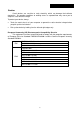
Caution Circuit devices are sensitive to static electricity, which can damage their delicate electronics. Dry weather conditions or walking across a carpeted floor may cause you to acquire a static electrical charge. To protect your device, always: • Touch the metal chassis of your computer to ground the static electrical charge before you pick up the circuit device. • Pick up the device by holding it on the left and right edges only.
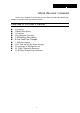
About this user’s manual In this user’s manual, it will not only tell you how to install and connect your network system but show you all the functions. Overview of this user’s manual 1. Overview 2. Model Description 3. Checklist 4. Installing the Converter 5. WDM Single Fiber Model 6. Link Fault Pass Through 7. LED Description 8. DC Jack and AC-DC Power Adapter 9. Connecting to TP, Fiber Device 10. Cable Connection Parameter 11.
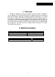
1. Overview IEEE802.3u 100Mbps Fast Ethernet supports two types of media, 10/100BaseTX and 100Base-FX, for network connection. The media converter has commercial and industrial different operating temperature optional specification. This media converter also supports POF (Plastic Optical Fiber) optional networking solution. It is suitable for in-door and out-door industrial Ethernet with fiber optical cable.
3. Checklist Before you start installing the Converter, verify that the package contains the following: — The TP-Fiber Converter — AC-DC Power Adapter or Self Powering Cable(USB) (upon the model user purchases) — This User's Manual Please notify your sales representative immediately if any of the aforementioned items is missing or damaged. 4. Installing the Converter Wear a grounding device for electrostatic discharge 4.
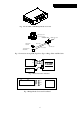
Fig. 1 Front View of LFP Bridge Media Converter USB A Type Jack USB Cable USB B Type Jack Fiber Optic 100FX Fiber Network RJ-45 Jack Cat. 5 Cable 10/100 Ethernet Switch/NIC Fig. 2 Connection among USB (Type B-to-Type A Plug), Fiber and TP Cables RX TX TX RX TP-to-100FX Converter 10/100Base-TX Network Fig. 3 Basic Network Connection TX RX FX TP LNK /ACT 100 FDX /COL PWR Fig.
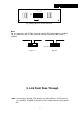
HDX-FX HDX 10 FORCE LFP DIS 5 FDX 4 LFP 3 FDX 2 100 1 AUTO S1 TP Fig. 5 Bridge Media Converter Side Panel Note: Fig. 6-1 represents that TP-Fiber Converter with AC-DC Power Adapter is enabled; Fig. 6-2 represents that TP-Fiber Converter with Self Powering Cable (USB) is enabled. 5VDC 5VDC USB Slide Switch USB Slide Switch Fig. 6-1 Fig. 6-2 5. Link Fault Pass Through Note: Link fault pass through (LFP) function only takes effect as S1-Bit4 (see Fig. 13) is enabled.
This media converter supports link fault pass through (LFP) in TX/FX converter application. Link status on one port is propagated to the other port to notice the remote nodes. If TP port is unplugged, this converter stops transmission on fiber port. This causes the remote fiber node link to fail. LED shows the link failure on both TP and fiber ports. If fiber link fails, this converter restarts auto-negotiation on TP port but always stays in the link failure state.
6. LED Description LED Color FX LNK/ACT Green FX FDX/COL Amber TP LNK/ACT Green TP 100 Green PWR Green Function Lit when fiber connection is good Blinks when fiber data is present Lit when full-duplex mode is active Off when half-duplex is active Blinks when collision is present Lit when TP connection is good Blinks when TP data is present Lit when TP speed is 100Mbps Off when TP speed is 10Mbps Lit when +5V power is coming up 7. DC Jack and AC-DC Power Adapter The DC jack's central post is 2.
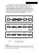
8. Connecting to TP, Fiber Device Converter TP Port 10/100TP Converter Fiber Port 100FX AUTO, FORCE selectable: Bit 1, 2, 3 of S1 a. AUTO: 10/100 NWay Auto-negotiation b. FORCE: 100 or 10, FDX or HDX 100Mbps duplex selectable: Bit 5 of S1 a. FDX for 100FDX fiber link partner, default b. HDX for 100HDX fiber link partner TP-AUTO 100 FDX LFP EN FDX-FX S1 TP-FORCE 10 HDX LFP HDX-FX DIS Fig.
9. Cable Connection Parameter 100Base-X network allows 512-bit time delay between any two node-stations in a collision domain. Switch-based Media Converter breaks up TP and Fiber segments’ collision domain to extend the cabling distance. TP Cable Limitations: Cat. 5 and up to 100m Converter Fiber Cable Limitations: SC/ST Converter Models Multi-mode Half-duplex Multi-mode Full-duplex Single-mode Half-duplex Single-mode Full-duplex 412m 2Km 412m 15Km 10. TP-Fiber Technical Specifications • • :IEEE802.