
User Guide

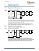
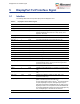
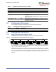
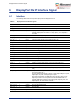
Table Of Contents

DisplayPort Tx IP Interface Signal
Microsemi Proprietary and Confidential UG0935 User Guide Revision 2.0 7
5 DisplayPort Tx IP Interface Signal
5.1 Interface
The following table shows the input and output ports for DisplayPort Tx IP.
Table 2 • DisplayPort Tx IP Interface signals
Interface Width Direction Description
vclk_i 1 Input Video clock
vrst_n_i 1 Input Low-active reset signal synchronized with vclk_i
dpclk_i 1 Input DisplayPort IP working clock. It is DisplayPortLaneRate/40. For
example, DisplayPort lane rate is 2.7 Gbps, dpclk_i is 2.7
Gbps/40 = 67.5 MHz.
dprst_n_i 1 Input Low-active reset signal synchronized with dpclk_i
aux_clk_i 1 Input AUX Channel clock. It is 100 MHz.
aux_rst_n_i 1 Input Low-active reset signal synchronized with aux_clk_i
pclk_i 1 Input APB interface clock
prst_n_i 1 Input Low-active reset signal synchronized with pclk_i
paddr_i 16 Input APB address
pwrite_i 1 Input APB write signal
psel_i 1 Input APB select signal
penable_i 1 Input APB enable signal
pwdata_i 32 Input APB writing data
prdata_o 32 Output APB reading data
pready_o 1 Output APB reading data ready signal
async_mvid_i 24 Input Mvid for asynchronous video clock mode, this signal should be
synchronized with dpclk_i. This signal would be ignored for
synchronous video clock mode.
int_o 1 Output Interrupt signal to CPU
vsync_i 1 Input VSYNC for input video stream. It should be synchronous with
vclk_i.
hsync_i 1 Input HSYNC for input video stream. It should be synchronous with
vclk_i.
pixel_val_i 1/2/4 Input Indicates the validation of pixels on pixel_data_i port,
synchronous with vclk_i
pixel_data_i 48/96/192 Input Input video stream pixel data. It could be 1, 2, or 4 parallel
pixels. It should be synchronous with vclk_i.
For four parallel pixels, bit[191:144] for 1
st
pixel, bit[143:96] for
2
nd
pixel, bit[95:48] for 3
rd
pixel, and bit[47:0] for 4
th
pixel.
Each pixel uses 48 bits, for RGB, bit[47:32] is R, bit[31:16] is G,
bit[15:0] is B. Each color component uses the lowest BPC bits.
For example, RGB with 24 bits per pixel, bit[7:0] is B, bit[23:16]
is G, and bit[39:32] is R. All other bits are reserved.
hpd_i 1 Input HPD input signal