
User Guide

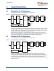
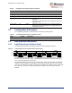
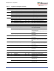
Table Of Contents

Typical Application
Microsemi Proprietary and Confidential UG0935 User Guide Revision 2.0 6
4 Typical Application
4.1 DisplayPort Tx IP Application
The following figure shows the typical DisplayPort Tx IP application.
Figure 3 • Typical application for DisplayPort Tx IP
As shown in the preceding figure, the RGB input module interface gets a video stream signal. The Image
Processing module processes the video stream according to system requirements. It outputs the video
stream to DisplayPort Tx IP. DisplayPort Tx IP outputs four lanes data to the 8B10B encoder. After 10B
encoding, lanes' data are transmitted through Transceiver lanes.
Before video stream transmission, the DisplayPort Source application software which is running on
RISC-V, controls DisplayPort Tx IP to finish training work with the attached DisplayPort Sink device. To
do training and Link Policy Maker, all transactions are transmitted on the AUX Channel.
4.2 DisplayPort Rx IP Application
The following figure shows the typical DisplayPort Rx IP application.
Figure 4 • Typical application for DisplayPort Rx IP
As shown in the preceding figure, the transceiver block receives four lanes data. There are four
asynchronous FIFO to synchronize all lanes data into one clock domain. These four lanes data are
decoded to 8B code in 8B10B decoder modules. DisplayPort Rx IP gets lanes' 8B data and output video
stream data; it also works with RISC-V software to finish the training and Link Policy Maker. The
recovered video stream data is processed in the Image Processing module and generates output on the
RGB output interface.
RGB
Input
Image
Processing
DisplatPort Tx
IP
8B10B
Encoder
(x4)
Async
FIFO
(x4)
XCVR Tx
RISC-V
IRQ
AUX Out
AUX In
HPD
RGB
Output
Image
Processing
DisplatPort Rx
IP
8B10B
decoder
(x4)
Async
FIFO
(x4)
XCVR Rx
RISC-V
IRQ
AUX Out
AUX In
HPD