UG0935 User Guide DisplayPort IP
Microsemi Headquarters One Enterprise, Aliso Viejo, CA 92656 USA Within the USA: +1 (800) 713-4113 Outside the USA: +1 (949) 380-6100 Sales: +1 (949) 380-6136 Fax: +1 (949) 215-4996 Email: sales.support@microsemi.com www.microsemi.com ©2021 Microsemi, a wholly owned subsidiary of Microchip Technology Inc. All rights reserved. Microsemi and the Microsemi logo are registered trademarks of Microsemi Corporation. All other trademarks and service marks are the property of their respective owners.
Contents 1 Revision History . . . . . . . . . . . . . . . . . . . . . . . . . . . . . . . . . . . . . . . . . . . . . . . . . . . . . 1 1.1 1.2 Revision 2.0 . . . . . . . . . . . . . . . . . . . . . . . . . . . . . . . . . . . . . . . . . . . . . . . . . . . . . . . . . . . . . . . . . . . . . . . 1 Revision 1.0 . . . . . . . . . . . . . . . . . . . . . . . . . . . . . . . . . . . . . . . . . . . . . . . . . . . . . . . . . . . . . . . . . . . . . . . 1 2 Introduction . . . . . . . . . . . . . . . . . . .
8.4 8.5 8.6 DisplayPort Lanes Training . . . . . . . . . . . . . . . . . . . . . . . . . . . . . . . . . . . . . . . . . . . . . . . . . . . . . . . . . . 15 Video Stream Receiver . . . . . . . . . . . . . . . . . . . . . . . . . . . . . . . . . . . . . . . . . . . . . . . . . . . . . . . . . . . . . 16 Register Definition . . . . . . . . . . . . . . . . . . . . . . . . . . . . . . . . . . . . . . . . . . . . . . . . . . . . . . . . . . . . . . . . .
Figures Figure 1 Figure 2 Figure 3 Figure 4 Figure 5 Figure 6 DisplayPort Tx IP Implementation . . . . . . . . . . . . . . . . . . . . . . . . . . . . . . . . . . . . . . . . . . . . . . . . . . 3 DisplayPort Rx IP Implementation . . . . . . . . . . . . . . . . . . . . . . . . . . . . . . . . . . . . . . . . . . . . . . . . . . 4 Typical application for DisplayPort Tx IP . . . . . . . . . . . . . . . . . . . . . . . . . . . . . . . . . . . . . . . . . . . . . 6 Typical application for DisplayPort Rx IP . .
Tables Table 1 Table 2 Table 3 Table 4 Table 5 Table 6 Table 7 DisplayPort IP Resource Utilization . . . . . . . . . . . . . . . . . . . . . . . . . . . . . . . . . . . . . . . . . . . . . . . . . 4 DisplayPort Tx IP Interface signals . . . . . . . . . . . . . . . . . . . . . . . . . . . . . . . . . . . . . . . . . . . . . . . . . . 7 Configuration parameters for CoaXPress Host IP . . . . . . . . . . . . . . . . . . . . . . . . . . . . . . . . . . . . . . 8 DisplayPort Rx IP Interface signals . . . . . . .
Revision History 1 Revision History The revision history describes the changes that were implemented in the document. The changes are listed by revision, starting with the most current publication. 1.1 Revision 2.0 Removed the reference design demo information. 1.2 Revision 1.0 The first publication of this document. Microsemi Proprietary and Confidential UG0935 User Guide Revision 2.
Introduction 2 Introduction 2.1 Overview DisplayPort IP is targeted for the PolarFire FPGA application and includes DisplayPort Tx IP and DisplayPort Rx IP. These two IP implement part of the DisplayPort 1.4 Link Layer function. 2.2 Key Features The key features of DisplayPort Tx and Rx IP are listed as follows: • • • • • • 2.3 2.4 Support 1, 2, or 4 lanes. Support 8 bpc RGB/YCbCr 4:4:4 (24 bits per pixel). Support up to 8.1 Gbps per lane. Support DisplayPort 1.4 protocol.
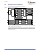
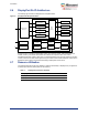
Introduction 2.5 DisplayPort Tx IP Architecture The following figure shows the DisplayPort Tx IP implementation.
Introduction 2.6 DisplayPort Rx IP Architecture The following figure shows the DisplayPort Rx IP implementation.
Functional Description 3 Functional Description 3.1 HPD DisplayPort Tx IP detects Hot Plug Detect (HPD) assertion, de-assertion, and HPD interrupt event. It reports the HPD event through an interrupt. After HPD assertion, which means a DisplayPort monitor is connected, DisplayPort Source application software should start the training procedure. DisplayPort Rx IP outputs HPD signal according to DisplayPort Sink application software settings.
Typical Application 4 Typical Application 4.1 DisplayPort Tx IP Application The following figure shows the typical DisplayPort Tx IP application. Figure 3 • Typical application for DisplayPort Tx IP RGB Input 8B10B Encoder (x4) Image Processing Async FIFO (x4) XCVR Tx DisplatPort Tx IP AUX Out AUX In HPD RISC-V IRQ As shown in the preceding figure, the RGB input module interface gets a video stream signal. The Image Processing module processes the video stream according to system requirements.
DisplayPort Tx IP Interface Signal 5 DisplayPort Tx IP Interface Signal 5.1 Interface The following table shows the input and output ports for DisplayPort Tx IP. Table 2 • DisplayPort Tx IP Interface signals Interface Width Direction Description vclk_i 1 Input Video clock vrst_n_i 1 Input Low-active reset signal synchronized with vclk_i dpclk_i 1 Input DisplayPort IP working clock. It is DisplayPortLaneRate/40. For example, DisplayPort lane rate is 2.7 Gbps, dpclk_i is 2.
DisplayPort Tx IP Interface Signal DisplayPort Tx IP Interface signals (continued) Table 2 • Interface Width Direction Description aux_tx_en_o 1 Output AUX Tx data enable signal aux_tx_io_o 1 Output AUX Tx data aux_rx_io_i 1 Input AUX Rx data dp_lane_k_o 16 Output DisplayPort output lanes' data K indication. It is synchronous with dpclk_i. Bit[15:12] for Lane0, bit[11:8] for Lane1, bit[7:4] for Lane2, and bit[3:0] for Lane3. dp_lane_data_o 128 Output DisplayPort output lanes' data.
DisplayPort Rx IP Interface Signal 6 DisplayPort Rx IP Interface Signal 6.1 Interface The following table shows the input and output ports for DisplayPort Rx IP. Table 4 • DisplayPort Rx IP Interface signals Interface Width Direction Description vclk_i 1 Input Video clock vrst_n_i 1 Input Low-active reset signal synchronized with vclk_i dpclk_i 1 Input DisplayPort IP working clock. It is DisplayPortLaneRate/40. For example, DisplayPort lane rate is 2.7 Gbps, dpclk_i is 2.7 Gbps/40 = 67.
DisplayPort Rx IP Interface Signal DisplayPort Rx IP Interface signals (continued) Table 4 • Interface Width Direction Description dp_lane_k_i 16 Input DisplayPort input lanes' data K indication. It is synchronous with dpclk_i. Bit[15:12] for Lane0, bit[11:8] for Lane1, bit[7:4] for Lane2, and bit[3:0] for Lane3. dp_lane_data_i 128 Input DisplayPort input lanes' data. It is synchronous with dpclk_i. Bit[127:96] for Lane0, bit[95:64] for Lane1, bit[63:32] for Lane2, bit[31:0] for Lane3.
DisplayPort Tx IP Configuration 7 DisplayPort Tx IP Configuration 7.1 HPD Detection DisplayPort Tx IP detects the input HPD signal to check the status of the attached DisplayPort Sink device. The HPD event includes three types. • • • HPD assertion, it means DisplayPort Sink device is connected. HPD de-assertion, it means DisplayPort Sink device is disconnected. HPD interrupt, it means the DisplayPort Sink device's status has changed.
DisplayPort Tx IP Configuration 7.4 DisplayPort Lanes Training At the first training stage, DisplayPort Tx IP should output TPS1 to get the attached DisplayPort Sink device to get LANEx_CR_DONE. The software should configure the following steps to enable TPS1 transmission: 1. 2. 3. Write enabled lane number into register 0x0004, it could be enabled 4 lanes, 2 lanes, or 1 lane. Write 0x01 into register 0x0018 to enable TPS1. Write 0x00 into register 0x0010 to disable scrambler.
DisplayPort Tx IP Configuration Table 6 • DisplayPort Tx IP Registers (continued) Address Bits Name Type Default Description 0x00D8 [15] MSA_HSync_Polarity RW 0x0 MSA_HSync_Polarity [14:0] MSA_HSync_Width RW 0x0 MSA_HSync_Width [15] MSA_VSync_Polarity RW 0x0 MSA_VSync_Polarity [14:0] MSA_VSync_Width RW 0x0 MSA_VSync_Width [7:1] MSA_MISC0_ColorIndicator RW 0x0 MSA_MISC0_ColorimetryIndicator [0] MSA_MISC0_SyncClock RW 0x0 MSA_MISC0_SynchronousClock [7:6] MSA_MISC1_Colo
DisplayPort Tx IP Configuration Table 6 • DisplayPort Tx IP Registers (continued) Address Bits Name Type Default Description [3] IntMask_HPD_IRQ RW 0x1 Interrupt mask for HPD IRQ. 1 enable interrupt [2] IntMask_AuxReplyTimeOut RW 0x1 Interrupt mask for AUX Reply Timeout. 1 enable interrupt [1] IntMask_NewAuxReply RW 0x1 Interrupt mask for received AUX Reply. 1 enable interrupt [0] IntMask_AuxTxDone RW 0x1 Interrupt mask for AUX Request transmission done.
DisplayPort Rx IP Configuration 8 DisplayPort Rx IP Configuration 8.1 HPD When the DisplayPort Sink device is ready and connected to the DisplayPort Source device, DisplayPort Sink application software should assert the HPD signal to 1 by writing 0x01 into register 0x0140. DisplayPort Sink application software should monitor the status of the sink device.
DisplayPort Rx IP Configuration When the source device is sending TPS3/TPS4 (Source device writes DPCD_0x0102 to indicates TPS3/TPS4 transmission), software should do the following steps to check if training is done: 1. 2. 3. 4. 5. Write enabled lanes number into register 0x0000. Write 0x00 into register 0x0014 to disable descrambler for TPS3. Write 0x01 to enable descrambler for TPS4. Waiting until Source device reading DPCD_0x0202 and DPCD_0x0203 DPCD registers.
DisplayPort Rx IP Configuration Table 7 • DisplayPort Rx IP Registers (continued) Address Bits Type Default Description [14:12] Lane3_RX_TPS_Mode RO 0x0 Lane3 received TPSx mode. 2 means TPS2, 3 means TPS3, and 4 means TPS4.
DisplayPort Rx IP Configuration Table 7 • DisplayPort Rx IP Registers (continued) Address Bits Name Type Default Description 0x012C [7:0] AUX_Rx_Request_Length RO 0x00 The number of bytes in the received AUX Request transaction 0x0140 [0] HPD_Status RW 0x0 Set HPD output value 0x0144 [0] Send_HPD_IRQ RW 0x0 Write to 1 to send a HPD interrupt 0x0148 [19:0] HPD_IRQ_Width RW 0x249F0 Defines the HPD IRQ low-active pulse width in aux_clk_i cycles 0x0180 [0] IntMask_Total_Interrup