SmartFusion2 MSS CAN Configuration
SmartFusion2 MSS CAN Configuration Table of Contents Introduction . . . . . . . . . . . . . . . . . . . . . . . . . . . . . . . . . . . . . . . . . . . . . . . . . . . . . . . . . . . . . . . . . . . . . . 3 1 Configuration Options. . . . . . . . . . . . . . . . . . . . . . . . . . . . . . . . . . . . . . . . . . . . . . . . . . . . . . . . . . . . . . . 4 2 Peripheral Signals Assignment Table . . . . . . . . . . . . . . . . . . . . . . . . . . . . . . . . . . . . . . . . . . . . . . . . . .
Introduction The SmartFusion2 Microcontroller Subsystem (MSS) provides one CAN hard peripheral (APB_1 sub bus). On the MSS Canvas, you must enable (default) or disable the CAN instance based on whether it is being used in your current application. When disabled, the CAN instance is held in reset (lowest power state). By default, when enabled, the CAN ports are configured to connect to the device Multi Standard I/Os (MSIOs). Note that MSIOs allocated to the CAN instance are shared with other MSS peripherals.
1 – Configuration Options There are no hardware configuration options for the CAN peripheral. Note: If the CAN instance is enabled, M3_CLK must be a multiple of 8MHz. This restriction will be enforced in the MSS CCC Configurator.
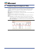
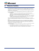
2 – Peripheral Signals Assignment Table The SmartFusion2 architecture provides a very flexible schema for connecting peripherals signals to either MSIOs or the FPGA fabric. Use the signal assignment configuration table to define what your peripheral is connected to in your application. This assignment table has the following columns (Figure 2-1): MSIO - Identifies the peripheral signal name configured in a given row.
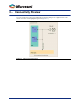
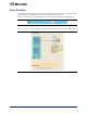
3 – Connectivity Preview The Connectivity Preview panel in the MSS CAN Configurator dialog shows a graphical view of the current connections for the highlighted signal row (Figure 3-1).
4 – Resource Conflicts Because MSS peripherals (MMUART, I2C, SPI, CAN, GPIO, USB, Ethernet MAC) share MSIO and FPGA fabric access resources, the configuration of any of these peripherals may result in a resource conflict when you configure an instance of the current peripheral. Peripheral configurators provide clear indicators when such a conflict arises.
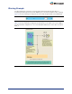
Error Example The USB peripheral is used and uses the device PAD bounded to package pin V24. Configuring the CAN peripheral such that the RXBUS port is connected to an MSIO results in an error. Figure 4-1 shows the error icon displayed in the Connectivity Assignment table for the RXBUS port. Figure 4-1 • Error Displayed in the Connectivity Assignment Table Figure 4-2 shows the error icon displayed in the Preview panel on the PAD resource for the RXBUS port.
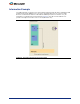
Warning Example The GPIO peripheral is used and uses the device PAD bounded to package pin V24 (GPIO_3). Configuring the CAN peripheral such that the RXBUS port is connected to an MSIO results in a warning. Figure 4-3 shows the warning icon displayed in the Connectivity Assignment table for the RXBUS port. Figure 4-3 • Warning Displayed in the Connectivity Assignment Table Figure 4-4 shows the warning icon displayed in the preview panel on the PAD resource for the RXBUS port.
Information Example The USB peripheral is used and uses the device PAD bounded to package pin V24. Configuring the CAN peripheral such that the RXBUS port is connected to the FPGA fabric does not result in a conflict. However, to indicate that he PAD associated with the RXBUS port (but not used in this case), the Information icon is displayed in the Preview panel (Figure 4-5). A tooltip associated with the icon provides a description of how the resource is used (USB in this case).
5 – Port Description Table 5-1 • Port Description Port Name RX Port Group CAN_PADS Direction In Description Local receive signal. CAN_FABRIC TX CAN_PADS Out CAN bus transmit signal. Out External driver control signal. / This is used to disable an external CAN transceiver. / TX_EN_N is asserted when the CAN controller is stopped or if the CAN state is bus-off. CAN_FABRIC TX_EN_N CAN_PADS CAN_FABRIC Note: • Port names have the name of the CAN instance as a prefix, e.g. CAN_RX.
A – Product Support Microsemi SoC Products Group backs its products with various support services, including Customer Service, Customer Technical Support Center, a website, electronic mail, and worldwide sales offices. This appendix contains information about contacting Microsemi SoC Products Group and using these support services. Customer Service Contact Customer Service for non-technical product support, such as product pricing, product upgrades, update information, order status, and authorization.
My Cases Microsemi SoC Products Group customers may submit and track technical cases online by going to My Cases. Outside the U.S. Customers needing assistance outside the US time zones can either contact technical support via email (soc_tech@microsemi.com) or contact a local sales office. Sales office listings can be found at www.microsemi.com/soc/company/contact/default.aspx.