
User Guide


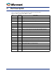

Table Of Contents

9
4 – Port Description
Table 4-1 lists the FIFO Controller without Memory signals in the generated macro.
Table 4-1 • FIFO Controller without Memory Signals
Port Direction Description
WE Input Write data into FIFO when signal is asserted
RE Input Read data from FIFO when signal is asserted
WCLOCK Input All signals in the write domain are synchronous to this clock
RCLOCK Input All signals in the read domain are synchronous to this clock
FULL Output Indicates that the FIFO is full
EMPTY Output Indicates that the FIFO is empty
RESET Input Asynchronous reset
AEMPTY Output Indicates that the FIFO has reached the Almost Empty threshold value
AFULL Output Indicates that the FIFO has reached the Almost Full threshold value
AEVAL[] Input Dynamic Almost empty threshold value
AFVAL[] Input Dynamic Almost full threshold value
WACK Output Indicates that a write on the FIFO succeeded
DVLD Output Indicates that a read on the FIFO succeeded
OVERFLOW Output Indicates that a write in the previous clock cycle failed
UNDERFLOW Output Indicates that a read in the previous clock cycle has failed
RDCNT[] Output The remaining number of READ domain elements in the FIFO
WRCNT[] Output The remaining number of WRITE domain elements in the FIFO
MEMWADDR [] Output Memory write address for external memory
MEMRADDR[] Output Memory read address for external memory
MEMWE Output Memory write enable for external memory
MEMRE Output Memory read enable for external memory
CLK Input Single Clock to drive WCLOCK and RCLOCK