SmartFusion2 FIFO Controller without Memory Configuration
SmartFusion2 FIFO Controller without Memory Configuration Table of Contents Introduction . . . . . . . . . . . . . . . . . . . . . . . . . . . . . . . . . . . . . . . . . . . . . . . . . . . . . . . . . . . . . . . . . . . . . . 3 1 Functionality . . . . . . . . . . . . . . . . . . . . . . . . . . . . . . . . . . . . . . . . . . . . . . . . . . . . . . . . . . . . . . . . . . . . . . 4 Write Depth/Width and Read Depth/Width . . . . . . . . . . . . . . . . . . . . . . . . . . . . . . . . . . . . . . . . . .
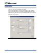
Introduction The FIFO Controller without Memory generates only the FIFO controller logic. This core is intended to be used along with either a Two-Port Large SRAM or a Micro SRAM. The FIFO Controller without Memory is independent of depth and width cascading of RAM Blocks. The FIFO Controller without Memory has single-RAM-location granularity with the empty / full flags. It supports many more optional status ports for increased visibility and usability.
1 – Functionality Write Depth/Width and Read Depth/Width The depth range for each port is 1-99999. The width range for each port is 1-999. The two ports can be independently configured for any depth and width. (Write Depth * Write Width) must equal (Read Depth * Read Width). Single Clock (CLK) or Independent Write and Read Clocks (WCLOCK, RCLOCK) The FIFO Controller without Memory offers a dual- or single-clock design. The dual clock design allows independent read and write clock domains.
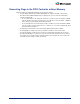
Generating Flags in the FIFO Controller without Memory Flags in the FIFO Controller without Memory are generated as follows: • The Full, Empty, Almost Full, and Almost Empty flags are registered outputs of this module. • The Almost Full and Almost Empty flags are optional ports; you can set the threshold values statically or dynamically.
2 – Area and Speed in the FIFO Controller The size and operating frequency of the FIFO Controller is dependent upon the configuration and optional features that are enabled; note that: • A single clock design will be smaller and faster; this is because the synchronizers and gray encoder/decoders are not required. • Port depths that are not a power of 2 will generate a larger and slower design. The reason is that logic optimization occurs for power-of-2 depths.
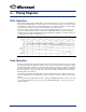
3 – Timing Diagrams Write Operation During a write operation when the WE signal is asserted the FIFO stores the value on the DATA bus into the memory. The WACK signal is asserted each time a successful write operation occurs on the FIFO. If the FIFO fills up, the FULL flag is asserted indicating that no more data can be written. The AFULL flag is asserted when the number of elements in the FIFO equals the threshold amount.
A sample timing diagram of a FIFO with depth configuration of 4, almost empty value set to 1, and rising clock edge is shown in Figure 3-2. Figure 3-2 • Read Operation and Flags Operations with a Variable Aspect Ratio A FIFO with variable aspect width has different depth and width configurations for the write and read side.
4 – Port Description Table 4-1 lists the FIFO Controller without Memory signals in the generated macro.
A – Product Support Microsemi SoC Products Group backs its products with various support services, including Customer Service, Customer Technical Support Center, a website, electronic mail, and worldwide sales offices. This appendix contains information about contacting Microsemi SoC Products Group and using these support services. Customer Service Contact Customer Service for non-technical product support, such as product pricing, product upgrades, update information, order status, and authorization.
My Cases Microsemi SoC Products Group customers may submit and track technical cases online by going to My Cases. Outside the U.S. Customers needing assistance outside the US time zones can either contact technical support via email (soc_tech@microsemi.com) or contact a local sales office. Sales office listings can be found at www.microsemi.com/soc/company/contact/default.aspx.