SmartFusion2 MSS MMUART Configuration
SmartFusion2 MSS MMUART Configuration Table of Contents Introduction . . . . . . . . . . . . . . . . . . . . . . . . . . . . . . . . . . . . . . . . . . . . . . . . . . . . . . . . . . . . . . . . . . . . . . 3 1 Configuration Options. . . . . . . . . . . . . . . . . . . . . . . . . . . . . . . . . . . . . . . . . . . . . . . . . . . . . . . . . . . . . . . 4 2 Peripheral Signals Assignment Table . . . . . . . . . . . . . . . . . . . . . . . . . . . . . . . . . . . . . . . . . . . . . . . . . .
Introduction The SmartFusion2 Microcontroller Subsystem (MSS) provides two MMUART hard peripherals (APB_0 and APB_1 sub busses) with Full/Half Duplex, Asynchronous/Synchronous mode and Modem interface option. On the MSS Canvas, you must enable (default) or disable each MMUART instance based on whether it is being used in your current application. Disabled MMUART instances are held in reset (lowest power state).
1 – Configuration Options Duplex Mode: • Full Duplex - Provides two signals for serial data, RXD and TXD • Half Duplex - Provides a single signal for serial data, TXD_RXD Async/Sync Mode - Selecting Synchronous mode provides a CLK signal. Modem Interface - Selecting the Modem interface enables access to individual ports in the MODEM port group.
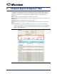
2 – Peripheral Signals Assignment Table The SmartFusion2 architecture provides a very flexible schema for connecting peripheral signals to either MSIOs or the FPGA fabric. Use the signal assignment configuration table to define what your peripheral is connected to in your application. The assignment table has the following columns (Figure 2-1): MSIO - Identifies the peripheral signal name configured in a given row.
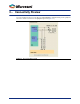
3 – Connectivity Preview The Connectivity Preview panel on the right of the MSS MMUART Configurator dialog shows a graphical view of the current connections for the highlighted signal row (Figure 3-1).
4 – Resource Conflicts Because MSS peripherals (MMUART, I2C, SPI, CAN, GPIO, USB, Ethernet MAC) share MSIO and FPGA fabric access resources, the configuration of any of these peripherals may result in a resource conflict when you configure an instance of the current peripheral. Peripheral configurators provide clear indicators when such a conflict arises.
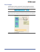
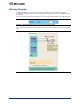
Error Example The USB peripheral is used and uses the device PAD bounded to package pin H27. Configuring the MMUART_0 peripheral such that the TXD_RXD port is connected to an MSIO will result in an error. Figure 4-1 shows the error icon displayed in the connectivity assignment table for the TXD_RXD port. Figure 4-1 • Error Displayed in the Connectivity Assignment Table Figure 4-2 shows the error icon displayed in the preview panel on the PAD resource for the TXD_RXD port.
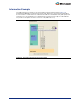
Warning Example The GPIO peripheral is used and uses the device PAD bounded to package pin H27 (GPIO_27). Configuring the MMUART_0 peripheral such that the TXD_RXD port is connected to an MSIO will result in a warning. Figure 4-3 shows the warning icon displayed in the connectivity assignment table for the TXD_RXD port. Figure 4-3 • Warning Displayed in the Connectivity Assignment Table Figure 4-4 shows the warning icon displayed in the preview panel on the PAD resource for the TXD_RXD port.
Information Example The USB peripheral is used and uses the device PAD bounded to package pin H27 (Figure 4-5). Configuring the MMUART_0 peripheral such that the TXD_RXD port is connected to the FPGA fabric does not result in a conflict. However, to indicate that he PAD associated with the TXD_RXD port (but not used in this case), the information icon is displayed in the preview panel. A tooltip associated with the icon provides a description of how the resource is used (USB in this case).
5 – Port Description Table 5-1 • Port Description Port Name TXD Port Group MMUART__PADS Direction Out MMUART__FABRIC RXD MMUART__PADS MMUART__PADS Serial output data in Full Duplex mode. This is the data that will be transmitted from Core16550. It is synchronized with the BAUDOUT output pin. In MMUART__FABRIC TXD_RXD Description Serial Input Data in Full Duplex mode. This is the data that will be transmitted into Core16550. It is synchronized with the PCLK input pin.
Table 5-1 • Port Description Port Name RI Port Group MMUART__PADS_MODEM Direction in \MMUART__FABRIC_MODEM DCD MMUART__PADS_MODEM MMUART__FABRIC_MODEM Description Ring Indicator. This active high signal is an input showing when the attached device (modem) has sensed a ring signal on the telephone line. Core16550 passes this information to the CPU via the Modem Status Register. This register also indicates when the RI trailing edge was sensed. In Data Carrier Detect.
A – Product Support Microsemi SoC Products Group backs its products with various support services, including Customer Service, Customer Technical Support Center, a website, electronic mail, and worldwide sales offices. This appendix contains information about contacting Microsemi SoC Products Group and using these support services. Customer Service Contact Customer Service for non-technical product support, such as product pricing, product upgrades, update information, order status, and authorization.
My Cases Microsemi SoC Products Group customers may submit and track technical cases online by going to My Cases. Outside the U.S. Customers needing assistance outside the US time zones can either contact technical support via email (soc_tech@microsemi.com) or contact a local sales office. Sales office listings can be found at www.microsemi.com/soc/company/contact/default.aspx.