
User Guide
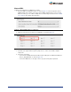
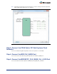


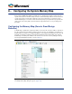
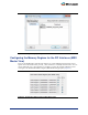

Table Of Contents
- Introduction
- 1 – MSS Configurator
- 2 – SmartDesign and MSS Configurator Actions
- 3 – Configuring the DDR_FIC Sub-System
- 4 – Configuring the SMC_FIC Sub-System
- 5 – Configuring the FIC Sub-Systems
- 6 – Configuring the FIC Sub-System Clocks
- 7 – Configuring the FIC Sub-System Reset
- 8 – Configuring the System Memory Map
- A – Product Support

29
Configuring the Memory Regions for the FIC Interfaces (MSS
Master View)
There are six 256 MB regions defined as FIC Regions 0 to 5 in the MSS memory map. Each of these
regions can be allocated to the FIC_0 or FIC_1 slave interfaces in a mutually exclusive fashion. You can
select to which FIC (0 or 1) slave interface you assign those regions by using the radio button next to
each region in the FPGA Fabric Address Regions (MSS Master View) group box (
Figure 8-3).
Figure 8-2 • Modify Memory Map Dialog Box
Figure 8-3 • FPGA Fabric Address Regions (MSS Master View)