
User Guide
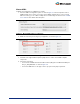
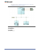
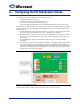


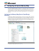
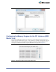

Table Of Contents
- Introduction
- 1 – MSS Configurator
- 2 – SmartDesign and MSS Configurator Actions
- 3 – Configuring the DDR_FIC Sub-System
- 4 – Configuring the SMC_FIC Sub-System
- 5 – Configuring the FIC Sub-Systems
- 6 – Configuring the FIC Sub-System Clocks
- 7 – Configuring the FIC Sub-System Reset
- 8 – Configuring the System Memory Map
- A – Product Support

28
8 – Configuring the System Memory Map
Each peripheral (AMBA AXI, AHBLite and APB3 slaves) is identified by an address from the FIC sub-
system's master point of view. We usually refer to the overall relationships between masters and slaves
of a sub-system as the memory map of that sub-system. The memory map of a sub-system can be
edited in SmartDesign. You can also view the final memory map of your system when you generate the
entire system. The memory map is part of the Datasheet generated for the 'root' of your design upon
generation.
Configuring the Memory Map (Generic SmartDesign
Behavior)
In SmartDesign, a peripheral is assigned an address on a bus based on the base address of that bus in
the sub-system plus the slot number on that bus times the slot size. So changing the slot number for a
peripheral affects its address accordingly. Changing the slot assignment for a peripheral can be done by
manually connecting the peripheral's slave BIF to a particular bus mirrored slave BIF (slot) using the
SmartDesign connectivity tools available in the Canvas. This can also be done by editing the memory
map using the Modify Memory Map, as shown in
Figure 8-1.
The Modify Memory Map dialog box appears (
Figure 8-2).
Figure 8-1 • Modify Memory Map from SmartDesign Canvas