
User Guide
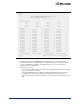
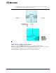

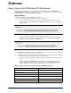
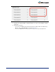
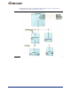
Table Of Contents
- Introduction
- 1 – MSS Configurator
- 2 – SmartDesign and MSS Configurator Actions
- 3 – Configuring the DDR_FIC Sub-System
- 4 – Configuring the SMC_FIC Sub-System
- 5 – Configuring the FIC Sub-Systems
- 6 – Configuring the FIC Sub-System Clocks
- 7 – Configuring the FIC Sub-System Reset
- 8 – Configuring the System Memory Map
- A – Product Support

18
Step 2: Create the FPGA Fabric FIC Sub-System
For each FIC interface exposed - master and slave, you must instantiate a bus (CoreAHBLite or
CoreAPB3) that matches the type you selected. Depending on the interface role (master/slave) and type
(AHBLite/APB3), the bus must be configured as follows:
Master/AHBLite
Instantiate and configure the CoreAHBLite bus as follows:
1. Select the Memory Space option that matches your requirements:
– If you need less than 16 MB of address space of all your peripherals, select the option as
shown in
Figure 5-3. This mode provides 16 16MB slots that can be used to connect up to 16
AHBLite slaves.
– If you need more than 16 MB and less than 256 MB of address space for any of your
peripherals, select the option as shown in
Figure 5-4. This mode provides 16 256 MB slots
that can be used to connect up to 16 AHBLite slaves.
2. Enable the slots that you are using for your application (
Figure 5-5). Best practice is to use the M1
to slot accesses as shown in
Figure 4-2 on page 15.
Note: Use M1 if you plan to create a multi master sub-system where you have a master in the fabric that
requires the remap feature and thus needs to be connected to M0.
– If you have selected the 16 MB per slot option, there are no restrictions on which slots can be
used.
– If you have selected the 256 MB per slot option, only the slots compatible with the FIC
instance fabric memory address regions selection can be used. Each FIC memory address
region is 256 MB in size. The six FIC memory regions are summarized in Ta b le 5 - 1.
Figure 5-3 • Master/AHBLite Memory Space Configuration - 16 MB per slot
Figure 5-4 • Master/AHBLite Memory Space Configuration - 256 MB per slot
Table 5-1 • Address Regions and Compatible Slots for 256 MB per Slot Option
Memory Address Region Compatible Slots
30000000-3FFFFFFF 3
50000000-5FFFFFFF 5
70000000-7FFFFFFF 7
80000000-8FFFFFFF 8
90000000-9FFFFFFF 9
F0000000-FFFFFFFF 15 (F)