
User Guide
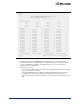
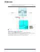

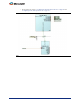
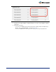
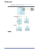
Table Of Contents
- Introduction
- 1 – MSS Configurator
- 2 – SmartDesign and MSS Configurator Actions
- 3 – Configuring the DDR_FIC Sub-System
- 4 – Configuring the SMC_FIC Sub-System
- 5 – Configuring the FIC Sub-Systems
- 6 – Configuring the FIC Sub-System Clocks
- 7 – Configuring the FIC Sub-System Reset
- 8 – Configuring the System Memory Map
- A – Product Support

15
Step 2: Create the FPGA Fabric SMC_FIC Sub-System
1. Instantiate and configure the CoreAXI such that the master slot M0 is enabled for the slave slot
S0, as shown in
Figure 4-2. Since you are addressing an external memory via a soft memory
controller, your slot size selection should match the amount of external memory space that you
plan on addressing from the Cortex-M3 processor or any master writing to that external memory
via the MSS DDR bridge.
2. From the IP Catalog, instantiate and configure CoreSDR_AXI to match your external memory
parameters.
3. Connect the sub-system (
Figure 4-3):
– Connect the MSS SMC_FIC master BIF port - MDDR_SMC_AXI_MASTER - to the CoreAXI
bus mirrored-master M0.
– Connect the CoreAXI mirrored-slave Bus Interface (BIF) port S0 to the slave BIF port of the
CoreSDR_AXI core instance.
Figure 4-2 • CoreAXI Configuration - SMC_FIC Mode