
User Guide
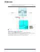
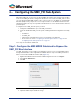

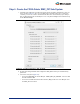
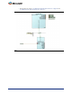
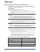
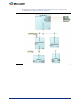
Table Of Contents
- Introduction
- 1 – MSS Configurator
- 2 – SmartDesign and MSS Configurator Actions
- 3 – Configuring the DDR_FIC Sub-System
- 4 – Configuring the SMC_FIC Sub-System
- 5 – Configuring the FIC Sub-Systems
- 6 – Configuring the FIC Sub-System Clocks
- 7 – Configuring the FIC Sub-System Reset
- 8 – Configuring the System Memory Map
- A – Product Support

13
4 – Configuring the SMC_FIC Sub-System
Although the SMC_FIC can be used as an AXI or AHBLite bus interface, this document only describes
how to use the SMC_FIC interface configured in AXI mode to connect to the CoreSDR_AXI core. That
core is an AXI-based SDR RAM controller used to connect, in this case, the MSS to an external Single
Data Rate (SDR) memory component. You can easily infer how to use the AHBLite interface from the
following description; the steps are very similar. The AXI interface is a more efficient interface and is the
preferred option.
To configure/create a SMC_FIC sub-system, you must:
1. Configure the MSS MDDR to expose the SMC_FIC interface
2. Create the FPGA fabric DDR_FIC sub-system, including instantiation/configuration/connectivity
for:
– CoreAXI bus
– CoreSDR_AXI
– Other masters and peripherals on the bus as required by your application
– Clocks and resets; refer to
"Configuring the FIC Sub-System Clocks" on page 23 and
"Configuring the FIC Sub-System Reset" on page 27
These steps are described in detail below.
Step 1: Configure the MSS MDDR Sub-block to Expose the
SMC_FIC Bus Interface
The SMC_FIC interface is exposed when your application needs to access an external SDR memory
through the FPGA fabric. In this configuration, the MDDR sub-block exposes the SMC_FIC interface,
which is a master AXI or AHBL Bus Interface (BIF) (
Figure 4-1).
1. Right-click the MDDR Controller inside the MSS Configurator and choose Configure.
2. Select Use an AXI Interface.
3. Click OK.
4. Update the MSS component with the change.
Figure 4-1 • MDDR Soft Memory Controller Configuration