
Spec Sheet

MECHANICAL
Weight (Standard): 2 oz. (57 g)
Weight (Right Angle): 2.8 oz. (87 g)
ENVIRONMENTAL
Housing: IP54 (category 2)
Operating Temperature: 0° to 50° C
(32° to 122°F)
Storage Temperature: –50° to 75° C
(–58° to 167°F)
Humidity: Up to 90% (non-condensing)
Operating Life: 40,000 hours at 25° C
CE MARK
General Immunity for Light Industry:
EN 55024: 1998 ITE Immunity Standard
Radiated and Conducted Emissions of ITE
Equipment: EN 55022:98 ITE Disturbances
LASER LIGHT
Type: Semiconductor visible laser diode
(650 nm nominal)
Safety Class: CDRH Class II, 1.0 mW max.
COMMUNICATION
Interface: RS-232, RS-422/485 (up to 115.2k),
Keyboard Wedge, USB
PROTOCOLS
Point-to-Point • Point-to-Point w/RTS/CTS •
Point-to-Point w/XON/XOFF • Point-to-Point
w/RTS/CTS & XON/XOFF • Polling Mode D
• Multidrop • User Dened • User Dened
Multidrop•Daisy Chain
SCANNING PARAMETERS
Options: single line, xed raster
Optional Raster: 7 raster lines over 1.5° arc (or
0.30” raster height at 4.5” [114 mm] distance)
Scan Rate: Adjustable from 300 to 1000
scans/second, default=500
Scan Width Angle: >70°
Pitch: ±50°
Skew: ±40°
Label Contrast: 25% min. @ 650 nm
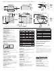
Note: Nominal dimensions shown. Typical tolerances apply.
SAFETY CERTIFICATIONS DESIGNED FOR
CDRH, FCC, UL/cUL, CE, BSMI
ROHS/WEEE COMPLIANT
ISO CERTIFICATION
Certied ISO 9001:2008 Quality Management
System
©201
5 Microscan Systems, Inc. SP017G-EN-1013
Read Range and other performance data is determined using high quality Grade
A symbols per ISO/IEC 15415 and ISO/IEC 15416 in a 25° C environment.
For application-specic Read Range results, testing should be performed with
symbols used in the actual application. Microscan Applications Engineering is
available to assist with evaluations. Results may vary depending on symbol
quality. Warranty–For current warranty information on this product, please visit
www.microscan.com/warranty.
READ RANGES
Narrow-bar-width Read Range
HIGH DENSITY
.0033” (.084 mm) 2.3” to 2.6” (58 to 66 mm)
.005” (.127 mm) 2” to 3.1” (51 to 79 mm)
.0075” (.191 mm) 1.7” to 3.7” (43 to 94 mm)
.010” (.254 mm) 1.5” to 4” (38 to 102 mm)
LOW DENSITY
.0075” (.191 mm) 3” to 6” (76 to 152 mm)
.010” (.254 mm) 2” to 7” (51 to 178 mm)
.015” (.381 mm) 2” to 8” (51 to 203 mm)
.020” (.508 mm) 2” to 10” (51 to 254 mm)
CONNECTOR
Type: 3 ft. cable terminated with High Density
15-pin D-Sub socket connector
ELECTRICAL
Power: 5 VDC +/– 5 %, 200 mV p-p max. ripple,
260 mA @ 5 VDC (typ.)
DISCRETE I/O
Trigger Input: 3 to 24V rated
(1 mA @ 5 VDC)
New Master: 3 to 24V rated
(1 mA @ 5 VDC)
Outputs (1, 2, 3): 5V TTL compatible,
can sink 10 mA and source 2mA
SYMBOLOGIES
Code 39, Codabar, Code 128,
Interleaved 2 of 5, Code 93, UPC/EAN,
Pharmacode, PDF417 (option)
INDICATORS
Beeper: Good read, Match/Mismatch, Noread,
On/Off LEDs: 1 status, 1 power, 5 read
performance (representing percentage of
good decodes)
HOST CONNECTOR/PIN ASSIGNMENTS
High Density 15 Pin D-sub Socket Connector
Note: For Right Angle option, subtract 0.6” (15 mm) from read range. Read
ranges are based upon optimal scan speed for specic symbol density.
HIGH
DENSITY
SCAN
AREA
Pin Host Host/Aux Host In/
No. RS232 RS232 RS422/485 Out
1 Power +5 VDC In
2 TxD TxD TxD(–) Out
3 RxD RxD RxD(–) In
4 Power/Signal Ground
5 NC
6 RTS Aux TxD TxD(+) Out
7 Output 1 TTL
a
Out
8 Default conguration
b
In
9 Trigger In
10 CTS Aux RxD RxD (+) In
11 Output 3 TTL
a
Out
12 New Master (NPN) In
13 Chassis ground
c
14 Output 2 TTL
a
Out
15 NC
a. Can sink 10 mA and source 2 mA.
b. The default is activated by connecting pin 8 to ground pin 4.
c. Chassis ground: Used to connect chassis body to earth
ground only. Not to be used as power or signal return.
MS−3 Bar c o de Scanner SpecificationS and optionS
LOW
DENSITY
SCAN
AREA
Microscan Systems Inc.
Tel 425 226 5700 / 800 251 7711
Fax 425 226 8250
Microscan Europe
Tel 31 172 423360 / Fax 31 172 423366
Microscan Asia Pacific
Tel 65 6846 1214 / Fax 65 6846 4641
www.microscan.com
Product Information: info@microscan.com
Technical Support: helpdesk@microscan.com