
Installation, Operation and Warranty Information Owner manual

12
DOC No: 7046 REV G
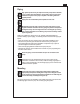
Do not overtighten fittings or leave them loose and susceptible to leaks. Refer
to the fitting manufacturer’s installation instructions for torque values.
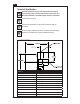
Ensure that inlet and discharge pipes are connected correctly in relation
to the direction of flow arrow marked on the pump.
Fittings
It is recommended that the pipe fittings are connected to the pump before the pump/
motor is fitted into the installation. The following should be observed when connecting
pipe fittings:
• Pipe sealing compound or PTFE tape should be applied to the threads to prevent
leakage.
• Apply sealant or tape sparingly to prevent a build up of excess material which may
dislodge and clog the pump. Two wraps of PTFE tape are usually sufficient.
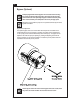
• Secure the pump in a vice (use pads to protect the pump body) and support the
motor when installing fittings.
• Ensure all joints are airtight.
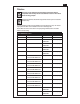
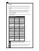
• Ensure all fittings are of the correct size for the pump being installed, refer to the table
below for correct sizing:
RECOMMENDED TUBING
Model Port Minimum Tubing
SERIES CA 3/8” NPT 12.5mm (1/2”)
SERIES GA 1/8” NPT 6.5mm (1/4”)
SERIES GAH 1/8” NPT 6.5mm (1/4”)
SERIES GAP MANIFOLD 6.5mm (1/4”)
SERIES GAT 1/4”-28 UNF
OR MANIFOLD
1.6mm (1/16”)
OR 6.5mm (1/4”)
SERIES GB 1/8” NPT 6.5mm (1/4”)
SERIES GC 3/8” NPT 12.5mm (1/2”)
SERIES GD 3/8” NPT 12.5mm (1/2”)
SERIES GJ 1/8” NPT 6.5mm (1/4”)
SERIES GK 1/4” NPT 10mm (3/8”)
SERIES GL 3/4” NPT 12.5mm (1/2”)
SERIES GM 3/4” NPT 25.4mm (1”)
SERIES GN 3/4” NPT 25.4mm (1”)
SERIES PD 1/4”-28 UNF 1.6mm (1/16”)
SERIES PF 1” BARB INLET
1/2” OUTLET
12.5mm (1/2”)
CAUTION