OWNERS MANUAL LUNATEC V2 MICROPHONE PREAMPLIFIER PO Box 204 Boulder, CO. 80306 voice: 303.443.7454 fax: 303.444.4634 email: info@gracedesign.
Thank you for purchasing the Lunatec V2 portable microphone preamplifier. It is designed and built to be extremely reliable and easy to use. This owner's manual includes important setup and operation instructions. Please take the time to familiarize yourself with these instructions which will help to avoid most common user problems. Grace Design has been building professional audio products for the recording industry for over ten years.
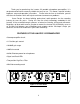
FRONT PANEL CONTROLS GAIN CONTROL Each gain control has 11 positions and adjusts the voltage gain from 10dB to 60dB in 5dB steps. TRIM CONTROL The trim control provides 10dB of continuously variable output attenuation. In the fully clockwise position the trim is at unity (no attenuation). In the fully counter-clockwise position the trim is at -10dB. For reference, the 3 o’clock position is -4dB and the 12 o’clock position is -8dB.
CONNECTING THE PREAMPLIFIER AUDIO CONNECTIONS Input connections are made using female XLR connectors. These are wired with pin 2 positive, pin 3 negative and pin 1 ground. 48V phantom power, if used, is supplied on pins 2 and 3. Output connections are made using male XLR connectors or RCA phono jacks. The XLR connectors are wired with pin 2 positive, pin 3 negative and pin 1 ground. Use the RCA phono jacks for unbalanced output.
OPERATION SETTING THE GAIN Turn the gain control fully counter-clockwise, turn the trim control fully clockwise and check that the +48V phantom power is off. Connect the microphone to the preamplifier and then turn the phantom power switch on if required. When sending a signal to a tape recorder that has fixed input levels, simply increase the gain until the optimum recording level is reached.
BATTERY CONSIDERATIONS With a standard pair of 48V condenser microphones the V2 draws roughly .48A. In our lab we have tested the V2 with an ECO-CHARGE Beta 6V 7.2A/h battery system. The V2 shuts down automatically after 13+ hours with a pair of Countryman Isomax II microphones. Note that this represents a complete discharge of a new and completely charged battery and if used in this fashion repeatedly the battery would degrade rapidly. 10 hours would be a conservative estimate..
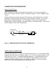
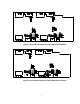
Figure 3. Circuit Board Jumper Locations SN #V054 and below Figure 4.
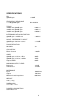
SPECIFICATIONS EIN @60dB gain <130dB FREQUENCY RESPONSE +/- 3dB @60dB gain: 6Hz-250kHz THD+N +20dBu out @20dB gain +20dBu out @40dB gain +20dBu out @60dB gain 0.0011% 0.0011% 0.0046% INTERMODULATION DISTORTION @40dB gain +25dBu out <.0025% NOISE - REFERRED TO INPUT @60dB gain 50 Ohm source <-130dB PHASE DEVIATION 50-20Khz <8° CROSSTALK Either Channel -109dB CMRR @60dB gain, 3.5Vcm, 1KHz @60dB gain, 3.