
User`s guide


User’s Guide
4
Power On Self-Test (POST) Codes
Most AT and 386 computers (and a few XT computers) output status codes during POST. The
Diagnostic Card displays these codes during and after POST. Refer to Appendix A for a
comprehensive listing of POST codes provided by BIOS manufacturers.
PCI Signal Definition:
CLK
Motherboard Clock Signal. Should be on when power is supplied to the
motherboard even without CPU.
BIOS
BIOS Read Signal. Flashes when CPU reads BIOS code.
IRDY
Device Ready. Flashes when an IRDY signal is detected.
OSC
ISA Oscillation Indicator. Indicate ISA Oscillation Signal is available.
FRAME
PCI Bus Frame. Should be on under normal circumstances and flashes
when a PCI Frame Signal is detected.
RST
SYS
DATA
IOW
Reset. After power on or reset, this indicator should be on for an half
second and then turned off.
Bus pulse. If the LED blinks, the main board bus is running. If the bus is
not running, the LED is off.
Data Transfer. This signal shows that a device has been selected for data
transfer. If no blink, the bus controller could be faulty.
I/O Write. Lights when the BIOS writes to device and provides the same
troubleshooting clues as the I/O READ.
12V
Power Supply, 12-Volt Positive. Should be on all the time otherwise there
is a short circuit.
-12V
Power Supply, 12-Volt Negative. Should be on all the time otherwise there
is a short circuit.
5V
Power Supply, 5-Volt Positive. Should be on all the time otherwise there is
a short circuit.
-5V
Power Supply, 5-Volt Negative. Should be on all the time otherwise there
is a short circuit.
3V3
Power Supply, 3.3-Volt. Some motherboards have 3.3V power supply to
PCI slots. This indicator should be on if the motherboard supplies 3.3V
power.
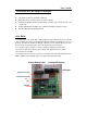
INSTALLING the Diagnostic Card
Installation Procedure
TO INSTALL A Diagnostic Card:
1) Install the Diagnostic Card in any available PCI or ISA expansion slot.
2) Power on the machine.
3) Install JP2 External Speaker Connection if required, see note below.
4) Observe POST CODE.