M5Pi PCI/ISA 60/66MHz Pentium Processor System Board Manual Document Number: 06-00096-05, Rev. 1B October 1994 221 Warren Ave.
Copyright Notices Micronics Computers, Inc. The information contained in the M5Pi system board manual has been carefully checked and is believed to be accurate. Micronics assumes no responsibility for any inaccuracies that may be contained in this document. Micronics makes no commitments to update or to keep the information in this manual at a current level when changes are made to the product. Micronics reserves the right to make improvements to this document and/or product at any time and without notice.
Micronics Quick Installation We know that many experienced people prefer to read as little of the documentation as possible. If this sounds like you, here’s the short form: 1. Ground yourself to prevent damaging static discharge, then remove the M5Pi from its packaging. 2. Configure and verify the system board’s jumper settings. (See Jumper Settings in Chapter 2) 3. Install the CPU and the system memory (Chapter 3). 4.
to configure. Press with Auto selected and the BIOS will automatically configure the drive for you. (See Chapter 4) 9. iv After you have configured the Main Setup menu, make any desired setting configurations in the Advanced and Security menu. When finished, go to the exit screen, select “Save Changes and Exit,” and you are finished with the BIOS configuration (Chapter 4).
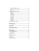
Contents Introduction ...................................................................... 1-1 Features ..................................................................................... 1-2 Software Compatibility ............................................................... 1-2 Configuring the M5Pi ....................................................... 2-1 Static Electricity .......................................................................... 2-1 Office Environment ..........................
Hard Disk 1-4 (IDE Drives Only) .............................................................. 4-4 Base Memory and Extended Memory ...................................................... 4-4 Video Card................................................................................................ 4-5 Keyboard ................................................................................................. 4-5 Setting the CMOS Extended Screen ........................................... 4-5 Serial Port A ....
List of Figures Figure 2-1: Figure 3-1: Figure 3-3: Figure 3-5: Figure 4-1: Figure 4-2: Figure 4-3: Figure 4-4: M5Pi System Board ...................................................................... 2-2 Installing a 72-Pin SIMM .............................................................. 3-5 Installing a PCI Peripheral Card .................................................... 3-7 Installing an ISA Card .................................................................. 3-8 Power-Up Screen ..............
viii
1 Introduction Congratulations for choosing the Micronics M5Pi! The M5Pi is a highperformance system board designed to be a foundation for serious computer applications. The M5Pi is a 60/66 MHz Pentium based board and is one of the most powerful Intel-based products on the market. The M5Pi comes with many built in features. These include support for four IDE hard drives, support for two floppy drives, a bi-directional parallel port, and two high speed serial ports.
Micronics M5Pi System Board Manual Features The M5Pi includes the following features: m Pentium processor support for 60MHz or 66MHz processors. m Two 32-bit PCI slots, four ISA slots, and one shared (PCI or ISA) slot. m 256K of L2 write-back cache. m Supports up to 128MB of on-board system memory. m Primary PCI Mode 3 IDE controller (supports two drives). m Secondary ISA IDE controller (supports two drives). m Floppy controller for two floppy drives (Supports 2.88MB, 1.44MB, 1.
2 Configuring the M5Pi Although the M5Pi system board is packaged in protective materials, it is important to use care while unpacking and setting up. Static Electricity The M5Pi is shipped from the factory in an antistatic bag. To reduce the possibility of damage, it is important to neutralize any accumulated static charges on your body before handling the board. The best way to do this is to ground yourself using a special wrist or ankle strap.
Micronics M5Pi System Board Manual M5Pi Components Figure 2-1 M5Pi System Board 2-2
Jumper Settings Jumper Settings Table 2-1 lists the jumper settings to select the speed of the CPU installed in your system. Speed Jumper W25 W26 W27 60MHz (default) close open close 66MHz open close open Table 2-1 CPU Speed Selection Table 2-2 lists the jumper settings to select the type of video installed. Jumper W3 Function color (default) monochrome Setting close open Table 2-2 Video Selection Table 2-3 lists the jumper settings to enable or disable the PCI IDE controller.
Micronics M5Pi System Board Manual Table 2-5 lists the jumper settings to set the secondary IDE controller’s IRQ. If you set this for IRQ14, you must disable the PCI IDE controller (Table 2-4). Jumper W14 Function IRQ15 (default) IRQ14 Setting 2-3 1-2 Table 2-5 Secondary IDE Controller IRQ Selection Table 2-6 lists the jumper settings to select the DMA channel for the IDE port.
Jumper Settings Table 2-8 lists the jumper settings to select a DMA channel for the parallel port. Jumper W6 W7 Function DMA Channel 1 DMA Channel 3 DMA not used (default) DMA Channel 1 DMA Channel 3 DMA not used (default) Setting 1-2 2-3 open 1-2 2-3 open Table 2-8 Parallel Port DMA Channel Selection Table 2-9 lists the jumper settings for programming the Flash ROM.
Micronics M5Pi System Board Manual Table 2-11 lists reserved jumper settings. Do not reconfigure these jumpers.
Jumper Settings Table 2-12 lists the jumper settings for case and peripheral connections. Jumper J19 J20 J21 J18 Function PCI IDE Connector ISA IDE Connector Floppy Connector Parallel Port Connector J12 Serial Port (Com1) J11 Serial Port (Com 2) J9 J8 & J15 J10 AT Keyboard PS/2 Mouse and Keybd. Ext.
3 Installing the M5Pi, System Memory, CPUs and Peripherals This section explains how to install the M5Pi system board, SIMMs, CPUs, and peripherals. Warning: Before installing or removing any peripherals or components, make sure you have a clear work space and that you adhere to all anti-static precautions described on page 2-1. Micronics recommends only trained technicians operate on the system board.
Micronics M5Pi System Board Manual Installation of the M5Pi The installation of the M5Pi system board depends on the type of case you use. The M5Pi is a Baby AT size system board and you should be able to install it in most cases. Prior to installing the M5Pi, make sure you have a clear work space available and adhere to all anti-static precautions.
Installing System Memory and Add-On Peripherals System Memory System memory devices, commonly known as SIMMs (Single Inline Memory Modules), are necessary to operate the M5Pi system board. The M5Pi has four SIMM sockets and can be upgraded to 128 Megabytes of RAM. This section will explain the type of SIMMs supported, list the rules of adding memory to the M5Pi, give some examples of common memory configurations, and show how to physically install the new SIMMs.
Micronics M5Pi System Board Manual Common Memory Configurations The following table (Figure 3-1) lists the most common memory configurations. The M5Pi will accept any combination of SIMMs as long as the rules in the previous section are followed.
Installing System Memory and Add-On Peripherals Installing the SIMMs To install the SIMMs, locate the memory banks on the system board. Find the lowest bank number available (0,1,2,3) and work your way up. Perform the following steps to install the SIMMs: 1. Hold the SIMM so that the notched edge is aligned with the notch on the SIMM socket (Figure 3-1). 2. Insert the SIMM at a 45 degree angle. 3. Gently push the SIMM into an upright position until it “locks” into place (past the release tabs).
Micronics M5Pi System Board Manual Installing a CPU The M5Pi is designed to support 60 or 66MHz Pentium processors. Follow the steps below to install a processor: 1. Turn off the computer and remove the computer cover. 2. Locate the ZIF socket illustrated in Figure 2-1. 3. Lift the lever of the socket. 4. Locate pin 1 on the processor and pin 1 on the socket (Figure 2-1). Gently set the processor into the socket, making sure pin 1 on the processor and pin 1 on the socket are aligned. 5.
Installing System Memory and Add-On Peripherals Installing a PCI Peripheral Card Micronics PCI slots accommodate all PCI peripherals which the PCI 2.0 specifications. Complete the following steps to install a PCI card: 1. Turn the computer system off and remove the computer cover. 2. Choose an unused PCI slot and remove the slot cover. 3. Insert the card with the bottom edge level to the slot. Never insert the card at an angle! 4.
Micronics M5Pi System Board Manual Installing an ISA Peripheral Card Micronics ISA slots accommodate all standard ISA peripherals. Complete the following steps to install an ISA card: 1. Turn the computer system off and remove the computer cover. 2. Choose an unused ISA slot and remove the slot cover. 3. Insert the card with the bottom edge level to the slot. Never insert the card at an angle! 4. Carefully push the card straight down, making sure the card is fully inserted. 5.
4 The BIOS Setup Utility Configuration After the M5Pi system board and all hardware is installed, the system is ready for configuration. Before turning on the computer, make sure all cables are correctly connected and all jumpers are correctly set. It is recommended you keep the computer cover off the first time you boot the system. If you have any difficulties, they will be easier to correct. Initial Boot Up Power up the M5Pi.
Micronics M5Pi System Board Manual Setup The Setup procedure is built into the system. Setup begins after the completed system is powered up. Once the system is powered up and goes through a memory test, the following screen appears on your monitor: Figure 4-1 Power-Up Screen If the systems detects a configuration error, it displays an error message. After the error message, another message displays indicating the choice to “press to continue (boot up), or to run the Setup procedure.
The BIOS Setup Utility Running the Setup Procedure If the system halts while booting, press and the CMOS Main Screen (Figure 4-2) should appear with the prompt on the time line. If the system does not halt and a DOS prompt does appears (i.e., A:\ or C:\), press the , , and keys simultaneously to begin the Setup procedure. The M5Pi system board has two CMOS configuration screens: the Main Screen (Figure 4-2) and the Extended Screen (Figure 4-3).
Micronics M5Pi System Board Manual Setting the CMOS Parameters Before running the computer, certain parameters on the CMOS configuration screens must be set so the computer properly operates. First, set the parameters on the CMOS Main Screen, then press the PgUp/PgDn key, and set the parameters on the CMOS Extended Screen. Note: Some of the parameters are already set and should not be changed. Only change the settings if necessary.
The BIOS Setup Utility Video Card This sets the type of monitor required for your computer. The display peripheral supports VGA/EGA, CGA80, CGA40, Monochrome (MONO), or no monitor at all. Use the <+/-> keys to toggle between the options. Keyboard If the keyboard category is set to INSTALLED, the computer will test the keyboard during boot. If set for NOT INSTALLED, the system will ignore any keyboard errors and always attempt to boot.
Micronics M5Pi System Board Manual Serial Port B Serial Port 2 may be set for COM2 (default), COM4, or may be disabled. Be sure this setting does not conflict with any other peripherals. Parallel Port The parallel port may be set for LPT1 (default), LPT2, or may be disabled. Be sure this setting does not conflict with any other peripherals. Secondary IDE The ISA IDE controller can be set to ENABLED or DISABLED. Onboard Floppy The On Board Floppy controller can be set to ENABLED or DISABLED.
The BIOS Setup Utility System BIOS The System BIOS Option allows you to Shadow, Shadow & Cache, or Disable the BIOS Shadow on the system board. Choosing SHADOWED copies the system’s BIOS into RAM for faster execution. Choosing SHADOWED & CACHED caches the shadowed system BIOS for even higher performance. This allows you to take advantage of the high-speed 32-bit bus and the 70 nanosecond RAM. Use the <+/-> key to toggle between the options.
Micronics M5Pi System Board Manual Re-Configuring Your Computer Press the key to reach the Exit Pop-Up Screen. Now select to save and initialize the new Setup.
A POST Messages The following table lists the Power On Self Test (POST) messages, possible causes, and solutions. Message NO DISKETTE CONTROLLER DISKETTE DRIVE RESET FAILED Possible Cause Disk controller not found. Disk adapter has failed or is improperly configured. Solution Change the Configuration. Check the disk adapter. DISKETTE DRIVE A FAILURE Drive A failed or is missing. Check the A drive. DISKETTE DRIVE B FAILURE Drive B failed or is missing. Check the B drive.
Micronics M5Pi System Board Manual Message A-2 Possible Cause Solution FIXED DISK CONFIGURATION FAILURE The specified configuration is not supported. Correct the hard disk configuration. FIXED DISK CONTROLLER FAILURE The controller card has failed. Replace controller card. FIXED DISK X FAILURE (where X =0 or 1) The hard disk crashed. Press F1 to reboot or rerun SETUP. If this does not work, replace hard disk. HARD READ FAILURE- STRIKE F1 TO RETRY BOOT The hard disk failed.
POST Messages Message Possible Cause Solution DISKETTE READ FAILURE, or NOT A BOOT DISKETTE, or NO BOOT DEVICE AVAILABLE Hard/floppy disk failed or is not bootable. Replace the diskette with a bootable diskette and retry. DECREASING AVAILABLE MEMORY, or MEMORY FAILURE AT AAAAAAAA READ XXXX EXPECTING YYYY (where AAAAAAAA = failing address, XXXX=data read, and YYYY=data written) The memory data integrity failed. Check contact points between memory modules and system board.
B Beep Codes Beep codes are a series of beeps sent through the speaker which indicate a problem during POST. If text appears on the video screen, the M5Pi has completed POST; any other tone from the speaker indicates something other than a POST error. These tones are not described in Table B-1. The beep error codes are a series of three sets of beeps. The duration of the beep tones are constant, but the length of the pauses between the beeps varies.
Micronics M5Pi System Board Manual B-2 Beep code Contents Port 80h Description None 01h CPU register test in progress. 1-1-3 02h CMOS read/write failure. 1-1-4 03h ROM BIOS check failure. 1-2-1 04h Programmable interval timer failure. 1-2-2 05h DMA initialization failure. 1-2-3 06h DMA page register write/read failure. 1-3-1 08h RAM refresh verification failure. None 09h First 64K RAM test in progress. 1-3-3 0Ah First 64K RAM chip or data line failure (multi-bit).
Beep Codes Beep code Contents Port 80h Description 2-4-3 1Eh Bit 14 first 64K RAM failure. 2-4-4 1Fh Bit 15 first 64K RAM failure. 3-1-1 20h Slave DMA register failure. 3-1-2 21h Master DMA register failure. 3-1-3 22h Master interrupt mask register failure. 3-1-4 23h Slave interrupt mask register failure. None 25h Interrupt vector loading in progress. 3-2-4 27h Keyboard controller test failure. None 28h CMOS power failure and checks calculation in progress.
C Hard Disk Drive Types The following table lists the hard disk types supported by M5Pi.
Micronics M5Pi System Board Manual Type Cyl 29 512 30 615 31 989 32 1020 33 615 34 820 35 1024 36 1024 37 1024 38 823 39 615 40 615 41 917 42 1023 43 823 User 1 User 2 User 3 User 4 Auto Not Installed C-2 Hd 8 2 5 15 4 6 9 5 5 10 4 8 15 15 10 Pre 256 615 0 -1 -1 -1 1024 512 512 256 128 128 -1 -1 512 LZ 512 615 909 1024 615 820 1024 1024 1024 824 664 664 918 1024 823 Sec 17 17 17 17 26 26 17 17 26 17 17 17 17 17 17 Size (MB) 34 10 41 127 31 62 76 42 65 60 20 40 114 127 60
D Specifications Processor 60MHz or 66MHz Pentium processor. Chipset Intel 82430 PCI Set. CPU Clock Select Frequency synthesizer chip. Jumper selectable CPU selection. Form Factor Baby AT size (8.5" x 13.75"). 4 layer PCB. Expansion Four 16-bit ISA slots. Two 32-bit PCI slots. One shared ISA/PCI slot. BIOS Phoenix BIOS on 1MB Flash EPROM. Multiple sector transfer support. IDE speed selection. RAM Capacity 128MB Keyboard PS/2 (PS/2 version). AT-Compatible (AT version).
Micronics M5Pi System Board Manual Mode 3 support. Multiple sector transfer support. LBA support. Secondary IDE Support Supports two additional IDE hard disks. LBA support. Environmental Specifications The environment in which the M5Pi is located is critical. Micronics recommends the following environmental specifications: Temperature Range Operating: 50 to 104 degrees Fahrenheit (10 to 50 degrees Celsius). Non -Operating: 50 to 140 degrees Fahrenheit (10 to 60 degrees Celsius).
Battery Disposal Warning: DO NOT: open battery; dispose of in fire; recharge; put in backwards, mix with used or other battery types. May explode or leak and cause personal injury.
FCC Warning Statement This equipment has been tested and found to comply within the limits for a Class B digital device, pursuant to Part 15 of the FCC Rules. These limits are designed to provide reasonable protection against harmful interference in a residential installation. This equipment generates, uses and can radiate radio frequency energy and, if not used in accordance with the instructions, may cause harmful interference to radio communications.
Glossary BIOS: Basic Input Output System. Maintains and controls the entire functions of the computer. Cache: Fast memory used to enhance the efficiency and speed of the computer. CPU: Central Processing Unit. Essentially, the “brains” of the computer. Disk Drive: Either a hard disk or a floppy diskette. DRAM: Dynamic Random Access Memory. EISA: Extended Industry Standard Architecture. ISA: Industry Standard Architecture.
Limited Warranty Except as described below, Micronics warrants the products to be free from defects in material and workmanship in normal use for a period of one (1) year from date of purchase. Should any product fail to perform according to this warranty at any time during the warranty period, except as provided below, Micronics or its authorized service centers will, at Micronics’ option, repair or replace the product at no additional charge.
Micronics M5Pi System Board Manual Micronics will not be liable for any lost profits or any indirect, special incidental or consequential damages in connection with the product, even if Micronics has been advised of the possibility of such damages. Micronics makes no warranties or representations as to performance of products or as to service to distributor or to any person, except as set forth in Micronics; limited warranty accompanying delivery of product.