
RAIDBank4 Owner's Manual


RAIDBank4 Owner’s Manual
10
Communication and Control
RAID functions including creation, modification, and monitoring can be accomplished through
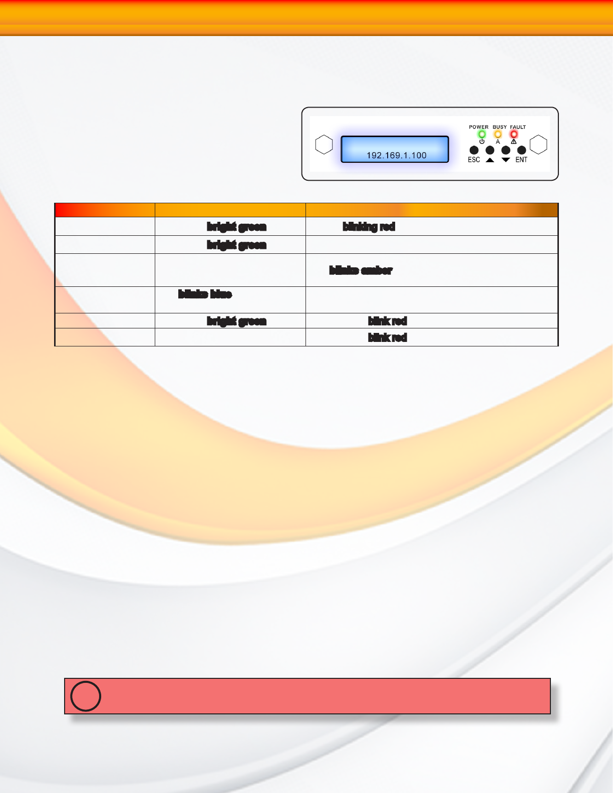
the LCD Control panel or the web based
administration user interface. The LCD status
panel informs you of the RAIDBank4’s current
operating status at a glance, as shown here:
MicroNet Tech
LED Normal Status Problem Indication
Power LED (Front) LED glows bright green Dark or blinking red on system error.
Power LED (LCD) LED glows bright green Dark on power-on
Busy LED LED is dark LED blinks amber
Disk Activity LED
LED blinks blue during hard
drive read and write activity
N/A
Disk Power LED LED glows bright green This LED will blink red if there is a disk error.
System Fault LED LED remains dark This LED will blink red if there is a system error.
Hot plug Drive Replacement
In the event of a drive failure, the RAIDbank4 supports the ability to hot-swap drives without
powering down the system. A data module can be removed and replaced without powering
off the unit or taking the system off line. In a fault tolerant array, the RAID rebuilding will
proceed automatically in the background (see Section 2.Understanding RAID for more
information.)
A drive failure will illuminate amber the drive indicator light above the failed drive on the
front of the RAIDBank4. To replace a drive, please follow these steps:
1. Press down on the drive release latch (see page 8, “The RAIDBank4 Interface components”)
to release the drive tray
2. Gently pull out the disk drive tray handle and slide out the drive tray.
3. To replace: Slide in the replacement drive tray with the tray handle open. When the tray is
slid all the way into the RAIDBank4, push the tray handle closed.
IMPORTANT: NEVER remove a drive tray without replacing it. Operating the RAID with a drive
tray missing will disrupt airflow and may cause the RAIDBank4 to fail.
!
1-Getting Started