
Installation Owner's manual


MOD 30ML Multiloop Controller
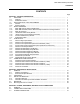
CONTENTS
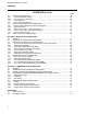
ILLUSTRATIONS
Figure Page
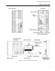
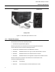
1-1 Location of Controller Components ...................................................................................... 3
1-2 MOD 30ML Split Architecture Version .................................................................................. 4
2-1 Example of an I/O Planning Form for a Controller with I/O Modules.................................... 25
2-2 1800R Controller Mounting Dimensions ............................................................................... 27
2-3 1803R Split Architecture Mounting Dimensions ................................................................... 28
3-1a Model C Electrical Connection Terminals............................................................................. 34
3-1b Models A & B Electrical Connection Terminals .................................................................... 35
3-2a Model C Terminal Identifications for Built-in I/O ................................................................... 40
3-2b Models A & B Terminal Identifications for Built-in I/O ........................................................... 40
3-3 Built-in Voltage, Millivolt and Thermocouple Input Connections........................................... 42
3-4 Built-in RTD Input Connections............................................................................................. 43
3-5 Built-in 2-Wire Milliampere Current Input Connections......................................................... 45
3-6 Built-in Non 2-Wire Current Input Connections .................................................................... 46
3-7 Built-In Resistance Input Connections.................................................................................. 47
3-8 Built-in Milliampere Output Connections............................................................................... 48
3-9 Built-in Voltage Output Connections..................................................................................... 49
4-1a Model C Terminal Identifications for Modular I/O ................................................................. 52
4-1b Models A & B Terminal Identifications for Modular I/O ......................................................... 52
4-2 Typical Connections for a 2013A Thermocouple Input Module, and a 2009A RTD
Module for Cold Junction Compensation.............................................................................. 55
4-3 Typical Connections for a 2004A Solid State Relay Input Module ....................................... 57
4-4 Typical Connections for a 2006A Nonisolated Digital Input Module..................................... 58
4-5 Typical Connections for a 2012A Current Input Module with 2-Wire Transmitter Power ..... 59
4-6 Typical Connections for a 2002A Current Input Module....................................................... 60
4-7 Typical Connections for a 2001A Voltage Input Module...................................................... 61
4-8 Typical Connections for a 2009A 2-Wire or 3-Wire RTD Input Module................................ 63
4-9 Typical Interface Circuit for 2020N Remote I/O Interface Module (RIO) .............................. 65
4-10 Typical Connections for a 2003A Current Output Module .................................................... 66
4-11 Recommended Connection to Solid State Relay..................................................................
67
4-12 Typical Connections for a 2005A Solid State Relay Output Module .................................... 68
4-13 Typical Connections for a 2007A Nonisolated Digital Output Module.................................. 69
4-14 Typical Connections for a 2011A Mechanical Relay Output Module (Dual SPST, NO/NC) 71
4-15 Typical Connections for a 2011AZ10200A Mechanical Relay Output Module (Form C) ..... 73
5-1a Model C Terminal Identifications for Communications Network Connections...................... 75
5-1b Models A & B Terminal Identifications for Communications Network Connections ............. 76
5-2 Locations for Port 1 Communications Jumper...................................................................... 78
5-3 ICN Connections for Built-in and Modular Communication Circuits .................................... 80
5-4 Typical Network Connections for Built-In Modbus RS-232 Communication ....................... 83
5-5 Typical Network Connections for Modular Modbus RS-232 Communication ..................... 84
5-6 Typical Modbus Connections for an RS-485, 2-Wire Network ............................................. 86
5-7 Simplified Diagram, 2034N RS-485, 4-Wire Module ............................................................ 88
5-8 Typical Modbus Connections for an RS-485, 4-Wire Network (Slave Controller)................ 89
5-9 Typical Modbus Connections for an RS-485, 4-Wire Network (Master Controller).............. 90
5-10 Typical Modbus Connections for a 4-Wire Master with 2-Wire Slaves................................. 91
A-1 Module Location Planning..................................................................................................... A-3
A-2 Model C Termination Wiring Planning .................................................................................. A-4
A-3 Models A & B Termination Wiring Planning.......................................................................... A-5
iii