MOD 30ML Multiloop Controller Scripting Hints, Help and Examples using 1800P MOD 30ML™ Identity Module and ViZapp Visual Application Designer Display Guide
MicroMod Automation, Inc. The Company MicroMod Automation is dedicated to improving customer efficiency by providing the most cost-effective, application-specific process solutions available. We are a highly responsive, application-focused company with years of expertise in control systems design and implementation. We are committed to teamwork, high quality manufacturing, advanced technology and unrivaled service and support.
Contents INTRODUCTION............................................................................................................ 1-1 1.1 Overview ............................................................................................................... 1-1 DISPLAY BASICS ......................................................................................................... 2-1 2.1 Overview ...............................................................................................................
MOD 30ML Display Guide Contents 4.4 Changing System Key Definition ........................................................................... 4-4 4.5 Using Multiple Display States................................................................................ 4-4 APPLICATION EXAMPLES........................................................................................... 5-1 2.1 Example 1: Basic PID Display .............................................................................. 5-2 2.
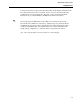
MOD 30ML Display Guide Introduction 1 2.1 Introduction Overview The MOD 30ML controller allows you to access virtually all its power through the operator display. The standard displays provide the generally accepted operating views for a three-term (P,I,D) control loop including graphic display of process setpoint and output, and alphanumeric display of loop tag, process value, setpoint/output values, and mode. Alarm and tuning pages are also provided.
MOD 30ML Display Guide Introduction 1-2
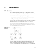
2 2.1 Display Basics Overview The only real limit to the number of display “pages” is database memory. Practical considerations such as operator preferences and plant philosophy will be the determining factors in the number of displays created for a single controller.
MOD 30ML Display Guide Display Basics The Display Interface Block (DIF) contains the list of all displays that can be shown on the operator display. The State Table block (ST) contains a file with lists of numbers to be translated into text on the displays. Because only one of these blocks is allowed per controller, the Display Interface Block and State Table Blocks are placed in the strategy automatically by the configuration software.
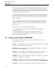
MOD 30ML Display Guide Display Basics Connections between the appropriate algorithm blocks and the Display and Tune blocks have already been made in the compounds. In most cases the user must make minor modifications to the blocks within the compound, or add to the State Table block. Instructions are provided in READ or NOTES blocks within each Symbol. The default ranges for PID blocks are 0 to 100 per cent, with local setpoint (the Cascade allows Local/Remote on the Slave).
MOD 30ML Display Guide Display Basics 2.2.1 Exercise: Loading and using a PID with display This exercise shows how to load the PID-100 compound. All default values are used. The resulting display will look similar to the diagram in the next figure. By holding down the Scroll key, tuning parameters can be accessed. Figure. 2 .2. Typical PID Loop display Exercise: Typical PID Loop and display 1. 3. 4. 5. 2 -4 Action Comment From the Gallery, export the ML_PID compound.
MOD 30ML Display Guide Display Basics In order for the new display to appear on the front panel during operation, you must place the Display Tag name in the Display List of the Display Interface Block, which manages displays in the controller. Figure 2 .3. Display Block Menu When the TAG key is pressed, displays will appear in the order in which they are listed in the Display List. Exercise: Typical PID Loop display (cont’d) 6. 7. 8. 9. 10. 11.
MOD 30ML Display Guide Display Basics If you wish to download the configuration and view the display, you must configure the appropriate communication block. The input ranges for the PID block are the default (0-100). Change these ranges in the Display (DISP) block: 1. Open the DISP block 2. Select Edit Display Formats 3. Change the Low Limit and High Limit for pvB, pvL, spB and spL to match the new ranges 4. Select ENTER 5.
MOD 30ML Display Guide Display Basics 2.3 Creating Custom Loops and Displays: An Overview There are five types of blocks that interact to display process information on the controller’s front panel: Display Blocks, Tune List Blocks, Process Alarm Display Blocks, the State Table Block and the Display Interface Block. The following sections describe the purpose and use of each block, followed by exercises demonstrating how to use them in display building.
MOD 30ML Display Guide Display Basics Figure 2 .4. Typical PID Loop display Although it is most common to use one display for one algorithm block (e.g. PID block), it is possible to combine attributes from several algorithm blocks into one display, or have multiple display blocks for a single algorithm block. The steps involved in creating a display are: 1. Determine the variables to be displayed and the format in which they will appear, using “Edit Inputs”. 2.
MOD 30ML Display Guide Display Basics Figure 2 .5. Display Block Menu Page 1 Bars refer to the three bargraphs on the controller display. Up to four highlighted segments may be defined, either by a constant value or by connection to another signal, in addition to the bar itself. Inputs are the values that will be shown on the front panel (either inputs from another block or local constants), or values that will be written from the front panel to logic or other functions.
MOD 30ML Display Guide Display Basics 2.3.2 State Table Block The State Table (ST) block is placed in the strategy automatically by Visual Application Designer. There is only one ST block per controller. Its sole function is to provide text that corresponds to codes in the controller, such as Auto/Manual, Local/Remote, etc.
MOD 30ML Display Guide Display Basics • manage the order in which displays appear on the front face • define how alarms are indicated and annunciated • set password protection for the controller. In order for a display to appear on the front face when the tag key is pressed, its Display Tag name must be in the Display List of the DIF block. If there are multiple displays for a control strategy, when the tag key is pressed displays will appear in the order in which they are listed in the Display List.
MOD 30ML Display Guide Display Basics 2.3.5 Process Alarm Display Blocks The Process Alarm Display (PAD) block combines the functions of detecting and signaling alarms, and displaying them on the front face of the MOD 30ML. It is NOT necessary to construct separate display blocks for alarms, unless the user desires custom alarm displays. Separate PAD blocks are used for each alarm trippoint desired. For example, a high process alarm, a low process alarm and a deviation alarm would require three PAD blocks.
MOD 30ML Display Guide Display Basics VCI Result AlarmInput PAD Figure 2 .9. Process Alarm Display Block Display Menu The Display Menu controls how the alarm will be indicated on the controller display. Alarms can be displayed numerically and graphically. When BAR is selected for Bar Format, the bar shows the alarm input with an intensified segment indicating the trip point.
MOD 30ML Display Guide Display Basics display is to the specified display. The name of the desired display must be entered in the field. For more information on Process Alarm Display blocks, see instruction manual IB1800R-APP, Section 2.6 2.4 Using Display Block Menus It is possible to create many displays without using Display Scripts or State Tables simply by filling in the fields in the main Display Block screens. A brief description of the relevant fields is given here. 2.4.
MOD 30ML Display Guide Display Basics Tag as the front face name by using the mnemonic DISPTAG on Line 1, as shown in the figure above. The Initial display state field is used to designate the script used initially by the display block. In most cases it will be DEFAULTS. If a script is not used, or if the display state is DEFAULTS, this field is left blank. Display States are described in more detail in Chapter 4.
MOD 30ML Display Guide Display Basics Figure 2 .12. Display Block Menu Bars Tab By entering all values as fixed, in double quotes, you can create a static screen that displays exactly what you have typed and does not change. Admittedly, this is not particularly useful in a process control environment. Therefore it is necessary to attach inputs to the display block and give them specific formats.
MOD 30ML Display Guide Display Basics 2.4.2 Display Block Inputs Selecting the Inputs tab brings up the Inputs menu. Up to 40 inputs, or attributes, may be entered in each Display block. To add inputs to the input list, click on the Add button. The dialog box Specify Input Data appears, as shown in Figure 12. Figure 2 .13.
MOD 30ML Display Guide Display Basics 2.4.3 Display Formats Selecting the Formats tab brings up the Formats menu. All attributes to be displayed must have an associated format; however several attributes may share a common format. For example, the process and setpoint bargraph displays usually use the same engineering units range. Therefore, a single format may be defined and used in the Inputs menu for the process input bar format and for the set-point bar format as well.
MOD 30ML Display Guide Display Basics The Display Format is selected using the pull-down menu. Table 2-1 shows the format types and how the data appears for each. For example, most analog variables such as Process and Setpoint are displayed as a Float, with one to six places to the right of the decimal point. Table 2 .1 Display Format Menu Display Format Used For Appears As Float0 Continuous (analog) variables X Float1 Continuous (analog) variables X.X Float2 Continuous (analog) variables X.
MOD 30ML Display Guide Display Basics Setting Entry Method to None causes the up/down arrows to remain invisible, and the variable cannot be changed from the front panel. If an engineering units label is desired, up to four characters may be entered in the Engineering Units field. This will cause the label to appear at the end of the displayed value, e.g., 175.6PSI. Only Floating Point and Integer display formats use Engineering Units.
MOD 30ML Display Guide Display Basics 2.4.4 Exercise: Creating an Indicating Totalizer using Display Block Menus Using only the Inputs menu, the Formats menu, and the entries on the main screen it is possible to construct many useful displays without creating either State Tables or Scripts. This exercise shows how to create an Indicating Totalizer display for use with a Totalizer block. The resulting display will look similar to the diagram shown in Figure 14. Figure 2 .15.
MOD 30ML Display Guide Display Basics Figure 2 .16. Totalizer Display for Exercise … 3. 4. 5. 6. 2 -22 Select the Initial/Restart tab of the Totoalizer block. Select Run as the Initial mode as shown in the next figure. Specify an Analog input to totalize. Any analog source may be connected to the blocks ANALINP, or a fixed value can be entered into Analog input Internal field on the General tab. Click on the OK button and close the Totalizer block This will be the initial mode for the totalizer.
MOD 30ML Display Guide Display Basics Figure 2 .17. Totalizer Display for Exercise … Exercise: Cont’d 7. 8. 9. 10. 11. 12. 13. Action From the System menu, place a DISP block in the strategy. Double-click to open the DISP block Comment In the Name field type a name such as DispTOT In the Description field type: Display total steam flow In the Display Tag field type STM TOT Type DISPTAG in the Line 1 Initial Value field This identifies this block within the database. It is NOT the display name.
MOD 30ML Display Guide Display Basics Figure 2 .18. Display Block General Menu Totalizer 14. 15. 16. 17. 18. Figure 2 .19. Display Block Input Dialog Box Totalizer Exercise: (cont’d) 2 -24 Select the Inputs tab. Select the Add button in the Inputs menu Give Input 1 the name: Total Leave the Data type as Floating point. In the Line Format field type: TotLine Close the menu with the OK button It is helpful to give the input a name that corresponds to the value to be displayed.
MOD 30ML Display Guide Display Basics 24. 25. Action Select the Formats tab, and select the Add button In the Name field, type: TotLine In the Format Type field, use the pulldown menu to select Float 0. Change the Entry Method field to None using the pull-down menu. Set the High Limit at 100000 by typing the value in the High Limit field In the Engineering Units field, type KLB. Close the dialog box using OK 26. Close the block using OK 19. 20. 21. 22. 23.
MOD 30ML Display Guide Display Basics Figure 2 .22. Display Interface Block – Display List 29. 30. 31. 2 -26 Click on OK to close the block. Save and Compile the database. Download the database to the controller.
MOD 30ML Display Guide Display Basics 2.5 Using State Tables In many applications it is useful to display more than one message in the same place. It is also helpful to be able to re-assign keys for various functions, such as clearing totalizers, advancing steps in a sequence or profile, turning a discrete device on or off, etc. The State Tables allow the user to show actual text on the front panel, for ease of operation.
MOD 30ML Display Guide Display Basics To determine correct values for an attribute refer to the Database Reference Manual for the corresponding block. Additional examples of State Tables for specific applications are shown later in the manual. The State Table names are entered in the Display Format section of the Display Block when the user wants to associate the text with the input.
MOD 30ML Display Guide Display Basics Figure 2 .24. Display Block Input 7. 8. In the Line Format field, type: clear Close the menu using the OK button 9. Select the Formats tab and click on the Add button. See next figure. In the Name field type: clear 10. 11. 12. 13. 14. 15. 16.
MOD 30ML Display Guide Display Basics Figure 2 .25. Display Block Formats – Clear Totalizer 17. Connect from Clear of the Display Block, to the RESINP input of the TOT block 18. 19. Close the loop compound. At the top level of the strategy, open the State Table (ST) block Select the Tables tab Scroll to the bottom of the State Table list. Leave one line after the last entry and add the following EXACTLY AS IT APPEARS BELOW: 20. 21. 22. clear, 3, “???” { 1, “YES”; 0, “NO”; } 23.
MOD 30ML Display Guide Display Basics Notes: 2 -31
MOD 30ML Display Guide Display Basics Notes: 2 -32
MOD 30ML Display Guide Display Scripts 3 3.1 Display Scripts General Display Scripts are used to: • create key macros to change things other than the bottom line • change how display resources are used, e.g. access custom tuning lists or “mutliplex” variables displayed in one place • manipulate data before displaying, e.g.
MOD 30ML Display Guide Display Scripts 3.1.3 Using A Common Script File For Multiple Display Blocks If using several Display blocks which all operate in the same way, i.e., key functions and display resource assignments are the same, a common display script file can be constructed that is shared by several Display Blocks. A benefit to a common display script file for multiple Display Blocks is that if a display script change is to be made it is made in one file only.
MOD 30ML Display Guide Display Scripts 3.2 The Display Script Language The display script language is used to develop custom displays or to modify displays that are found in the Compound library. A Display Script is a file associated with each Display Block, which consists of Display States, Event Scripts and Statements and uses the following general format: Figure 3 .1.
MOD 30ML Display Guide Display Scripts defined. For example, pressing the Scroll key may be used to change what is displayed on Line 6 most of the time, but under a particular circumstance might also be used to scroll through a custom menu permitting an operator to turn a valve on or off. For this example two Display States would be required along with an event that would cause the Display State to change. In each Display State the Scroll key is defined for a different function.
MOD 30ML Display Guide Display Scripts Pre-Defined Events Key Event ALARM_PRESSED TAG_PRESSED MANUAL_PRESSED AUTO_PRESSED RL_PRESSED SCROLL_PRESSED UP_PRESSED DOWN_PRESSED ALARM_HELD TAG_HELD MANUAL_HELD AUTO_HELD RL_HELD SCROLL_HELD UP_HELD DOWN_HELD ALARM_RELEASED TAG_RELEASED MANUAL_RELEASED AUTO_RELEASED RL_RELEASED SCROLL_RELEASED UP_RELEASED DOWN_RELEASED Display Event ENTRY ACTIVE EXIT When an Event occurs, the associated Event Script is executed.
MOD 30ML Display Guide Display Scripts Table 3 .2 Display Resource Names Constant: #RBAR #RISEG1 #RISEG2 #RISEG3 #RISEG4 #MBAR #MISEG1 #MISEG2 #MISEG3 #MISEG4 #LBAR #LISEG1 #LISEG2 #LISEG3 #LISEG4 #LINE1 #LINE2 #LINE3 #LINE4 #LINE5 #LED #BEEPER #UPDN #LINE6 Variable: #RBAR.SRC #RISEG1.SRC #RISEG2.SRC #RISEG3.SRC #RISEG4.SRC #MBAR.SRC #MISEG1.SRC #MISEG2.SRC #MISEG3.SRC #MISEG4.SRC #LBAR.SRC #LISEG1SRC #LISEG2.SRC #LISEG3.SRC #LISEG4.SRC #LINE1.SRC #LINE2.SRC #LINE3.
MOD 30ML Display Guide Display Scripts Figure 3 .2. Example: Display Resource Assignment DEFAULTS: { MANUAL_PRESSED: { #LINE5 = “OP”; #LINE6.SRC = OP; OPMS = 0; } (Display State name) (When manual key is pressed, then) (Line 5 reads OP) (Line 6 source is the Display Block Input called “OP”) (Output Mode is changed to 0 (manual)) In the above example, two inputs to the Display Block are the output (OP) attribute and the output mode status (OPMS) attributes of a PID block.
MOD 30ML Display Guide Display Scripts Table 3 .3 System Resources Display Definition Display Resource Name Assigned Value and Displayed Result Beeper 0 = Off 1 = On 3 - 65535 = Return to system definition 0 = Off 1 = On 3 - 65535 = Return to system definition 0 = No display 1 = Up arrow 2 = Down arrow 3 = slash 4 = Up arrow and slash 5 = down arrow and slash 6 = Up arrow, down arrow and slash 7 - 65535 = Return to system definition LED Up/Down Arrows 3.2.
MOD 30ML Display Guide Display Scripts IF I1 > 0 THEN IF I2 > I3 THEN I2 + 1 ELSE I3 + 1 IF I1 > 0 THEN { IF I2 > I3 THEN I2 + 1 } ELSE I3 + 1 In the example below, an IF-THEN-ELSE statement is combined with an assignment statement to toggle the value of a local display input, named SCRLCNT, between 1 and 0 each time the Scroll key is pressed: SCROLL_PRESSED: { IF SCRLCNT >= 1 THEN SCRLCNT = 0; ELSE SCRLCNT = SCRLCNT + 1; 3.2.
MOD 30ML Display Guide Display Scripts The example in Figure 3-4 combines an assignment statement, an IF-THEN-ELSE statement and a CASE statement to change what is displayed on Line 5 and Line 6 of the display, when the Scroll key is pressed. This is part of the standard Display Script supplied with Visual Application Designer. Figure 3 .4.
MOD 30ML Display Guide Display Scripts 3.2.7 RETURN Statement The RETURN statement indicates immediate exit from an event script. This prevents the script from performing any additional functions, including pre-defined system level functions. In other words, RETURN statements are used to keep the instrument operating system from taking over a key event that is normally defined by the system, when a custom script has been developed for that key.
MOD 30ML Display Guide Display Scripts Notes: 3 - 12
MOD 30ML Display Guide Special Effects 4 Special Effects In addition to creating loop displays, sequence displays and other operator displays, there are special effects that can easily be created, which emulate many operator terminal units. In many cases it may be possible to eliminate a separate operator interface device. 4.1 Marquee Messages Lines 1, 2 and 6 on the display may be used for “marquee” type messages of up to 15 characters.
MOD 30ML Display Guide Special Effects Figure 4 .2. Menu entries for marquee messages 4.2 Remote Display Input Normally, access to the different displays in the display list is controlled locally through the TAG key. However, the Display Interface (DIF) Block has an attribute called Remote Display Input. This is used to call up a specific display and normally prevents manual scrolling through any other display on the front face.
MOD 30ML Display Guide Special Effects 4.3 Auto-Scrolling Displays The MOD 30ML can scroll automatically and continuously through all displays in the Display List, with the option of manual intervention to stop and re-start the scroll action. If the operator must be able to stop the scrolling in order to view or operation the display, it is essential to choose a key that is NOT being used by the display for any other purpose.
MOD 30ML Display Guide Special Effects 4.4 Changing System Key Definition The following key functions are defined by the instrument operating system: • Alarm pressed – calls PAD and diagnostic alarm displays • TAG pressed – calls the next display in the Display List of the Display Interface Block • UP or DOWN arrow pressed – ramping of value on Line 6, if that value has been designated as operator adjustable in the Display Format.
MOD 30ML Display Guide Application Examples 5 Application Examples This section contains several examples of script definitions. In many cases one of these examples may be exactly what is required for the application. Any of the examples can be modified with custom script. It is usually easier to start with a known good script and modify it than it is to start from scratch. Each example of script is followed with printouts of the Display Block inputs and formats.
MOD 30ML Display Guide Application Examples 5.1 Example 1: Basic PID Display This display definition is contained in the pre-defined compound ML-PID (see Chapter 2). The script defines the functions of the Auto, Manual and Scroll keys. All other keys (Tag, Alarm, Up/Down Arrows) retain their standard functions as described in Chapter 4. Holding down the Scroll key calls up the Tune List parameters on Lines 5 and 6. Most of this script is discussed in detail in Chapter 3.
MOD 30ML Display Guide Application Examples The next figure shows the Display Block Inputs for this display. Figure 5 .2. Display Block Inputs, Basic PID Display The next figure shows the Display Formats for process, setpoint and output as digital readouts (pvL, spL, opL), process/setpoint and output as bargraphs (pvB, opB), and setpoint mode and output mode in conjuction with State Tables.
MOD 30ML Display Guide Application Examples Figure 5 .3.
MOD 30ML Display Guide Application Examples The next figure illustrates the menu entries in the Display menu of the Display Block. No highlighted segments are used in this example. Figure 5 .4. Display and Bar Menus, Basic PID Display Enter in Display List PID-100 appears on Line 1 The next figure lists the inputs for the Tuning displays.
MOD 30ML Display Guide Application Examples Figure 5 .5. Tune List Inputs, Basic PID Display Finally, the formats assigned to the Tuning parameters are shown in the next figure. The “T” in the Display State Table name was used by the author to designate Tuneable parameters in the State Tables. This is also how they are designated in the default State Table List provided with Visual Application Designer. Figure 5 .6.
MOD 30ML Display Guide Application Examples Figure 5 .7.
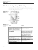
MOD 30ML Display Guide Application Examples 5.2 Example 2: Adding Remote/Local Setpoint Switching The PID100 Smart Symbol assumes the PID block uses local setpoint only, so no definition is needed for the R/L key. But many applications use a combination of Local and Remote setpoint and the operator must be able to switch between them from the front panel. This example adds the R/L key function to the Basic PID Display in Example 1.
MOD 30ML Display Guide Application Examples 5.3 Example 3: PID & Totalizer Operation on a Single Display In this example, one Tag display is used for PID loop operation and display/operation of an indicating totalizer. The Totalizer value and commands appear only when requested. This is the script used for the compound PIDTOT1 included in Visual Application Designer’s Project Gallery.
MOD 30ML Display Guide Application Examples { } IF SCRLCNT == 2 THEN #LINE6.SRC = ACTION; #UPDN = 7; If the value of SCRLCNT is 2 then assign a count input called ACTION to line 6. This count is displayed as a state value and shows the totalizer commands of RESET, STOP, RUN, HOLD and EXIT. ACTIVE: Arrow keys returned to “system” { control after operation IF ACTION && !DELTA THEN { CMDINP = ACTION; If value of ACTION is not 0 (EXIT), and DELTA = 1; value of DELTA is 0, then set CMDINP } equal to ACTION.
MOD 30ML Display Guide Application Examples The next figure illustrates the new Display Inputs that are added for this example. Figure 5 .11. Display Inputs, PID and Totalizer Two new formats are added to the formats shown in Example 1. These are shown in the next figure. They do not require any “Edit When” statements.
MOD 30ML Display Guide Application Examples Figure 5 .12.
MOD 30ML Display Guide Application Examples 5.4 Example 4: Variable Ramping with Two Keys The standard method of changing a variable on Line 6 is to press either the UP or DOWN arrow, use the FAST / SLOW keys to select the digit to be changed, then use the UP / DOWN arrows to make the change. Some operators may prefer a two-key operation to change the value of setpoint, output or other parameters.
MOD 30ML Display Guide Application Examples Figure 5 .13. Script for Two-Key Ramping DEFAULTS: { MANUAL_PRESSED: { IF OPMS != 3 THEN { OPMS = 0; #LINE5 = " OP"; #LINE6.SRC = OP; SCRLCNT = 0; } } AUTO_PRESSED: { IF OPMS != 3 THEN OPMS = 1; IF SCRLCNT == 0 THEN #UPDN = 0; } Change controller mode to manual when MAN key is pressed unless mode is TRACK. Force Line 6 to display Output value. Change controller mode to automatic when AUT key is pressed, unless mode is TRACK.
MOD 30ML Display Guide Application Examples Script for Two-Key Ramping (continued) /* Cause UP ramping of setpoint or output: */ IF UPHLD && OPMS == 0 && OP = OP + 0.01; ELSE IF UPHLD && OPMS == THEN OP = OP + 0.1; ELSE IF UPHLD && OPMS == THEN OP = OP + 1; ELSE IF UPHLD && SCRLCNT SP = SP + 0.01; ELSE IF UPHLD && SCRLCNT SP = SP + 0.
MOD 30ML Display Guide Application Examples Script for Two-Key Ramping (continued) ELSE DWNCOUNT = DWNCOUNT + 1; IF OP IF SP SCRLCNT == 0 THEN = OP - 0.1; SCRLCNT == 1 THEN = SP - 0.
MOD 30ML Display Guide Application Examples Figure 5 .14.
MOD 30ML Display Guide Application Examples 5.5 Example 5: Time-Based Variable Ramping In some controllers, the longer the up or down ramp key is held, the faster the variable changes. In this example, for the first two seconds the tenths digit will ramp at a rate of 0.2 counts per second. Then the ones digit will ramp at a rate of 2 counts per second for two seconds, and finally the tens digit will ramp at a rate of 20 counts per second, as illustrated in the next figure. Figure 5 .15.
MOD 30ML Display Guide Application Examples Figure 5 .16. Script for Two-Key Ramping DEFAULTS: { MANUAL_PRESSED: { IF OPMS != 3 THEN { OPMS = 0; #LINE5 = " OP"; #LINE6.SRC = OP; SCRLCNT = 0; } } AUTO_PRESSED: { IF OPMS != 3 THEN OPMS = 1; IF SCRLCNT == 0 THEN #UPDN = 0; } SCROLL_PRESSED: { IF SCRLCNT >= 1 THEN SCRLCNT = 0; ELSE SCRLCNT=SCRLCNT + 1; CASE SCRLCNT OF { 0: #LINE5 ="OP"; #LINE6.SRC= OP; IF OPMS == 0 THEN #UPDN = 7; BREAK; 1: #LINE5 = "SP"; #LINE6.
MOD 30ML Display Guide Application Examples /* Cause UP ramping of setpoint or output:*/ Script for Two-Key Ramping (continued) IF UPHLD && OPMS == 0 && OP = OP + 0.01; ELSE IF UPHLD && OPMS == THEN OP = OP + 0.1; ELSE IF UPHLD && OPMS == OP = OP + 1; ELSE IF UPHLD && SCRLCNT SP = SP + 0.01; ELSE IF UPHLD && SCRLCNT SP = SP + 0.
MOD 30ML Display Guide Application Examples Script for Two-Key Ramping (continued) RETURN; } DOWN_HELD: { DWNHLD = 1; RETURN; } /* Reset local inputs UPHLD and DWNHLD for next use: */ UP_RELEASED: { UPHLD = 0; RETURN; } DOWN_RELEASED: { DWNHLD = 0; RETURN; } } 5 - 21
MOD 30ML Display Guide Application Examples The next figure illustrates the new input definition required for this example: Figure 5 .17.
MOD 30ML Display Guide Application Examples 5.6 Example 6: Multiple Tune Lists In some applications it may be either desirable or necessary to use more than one Tune List block with a single Display Block. Uses of this feature might include: • the number of variables to be considered “tuneable” is greater than 40; • tuning parameters are to be grouped in different lists; or • Tune Lists are used for separate recipe definition. This example is uses the compound PID&DISP as a starting point.
MOD 30ML Display Guide Application Examples A symptom of incorrect occurrence number assignment is tuning one loop and affecting the tuning parameters of other loops. No new State Tables are required for this example; they are already contained in the Default State Tables supplied with Visual Application Designer.
MOD 30ML Display Guide Application Examples The script for this example is shown in the next figure: Figure 5 .18. Script for accessing multiple TuneLists DEFAULTS: { MANUAL_PRESSED: { IF OPMS != 3 THEN { OPMS = 0; #LINE5 = “OP”; #LINE6.SRC = OP; } } AUTO_PRESSED: { IF OPMS != 3 THEN { OPMS = 1: } } SCROLL_PRESSED: { IF SCRLCNT >= 2 THEN SCRLCNT = 0; ELSE SCRLCNT=SCRLCNT + 1; CASE SCRLCNT OF { 0: #LINE5 ="OP"; #LINE6.SRC= OP; BREAK; 1: #LINE5 = "SP"; #LINE6.SRC = SP ; BREAK; 2: #LINE5 = “TUN”; #LINE6.
MOD 30ML Display Guide Application Examples Display script for multiple tuning lists (Continued) …continued from previous page: Check to see that TUNING is false (no ACTIVE: tune list is already up).
MOD 30ML Display Guide Application Examples The next figure illustrates the new inputs that must be added to the Display Inputs menu: Figure 5 .19. Display Block Inputs, Multiple Tune Lists Next figure shows the new Format added for TUNE_REQ: Figure 5 .20.
MOD 30ML Display Guide Application Examples 5.7 Example 7: Start & Stop a Discrete Device Motors, pumps, solenoid valves and other discrete devices can be commanded from the MOD 30ML display, taking the place of separate display terminals or pushbuttons. This example illustrates stop and start of a motor. The Start/Stop commands and the feedback can be shown on the display. No display scripting is required for this strategy.
MOD 30ML Display Guide Application Examples The next figure illustrates the Display Menus, Display Inputs, and Display Formats for this example. Figure 5 .23.
MOD 30ML Display Guide Application Examples 5 - 30
MOD 30ML Display Guide Application Examples 5.8 Example 8: Recipe Selection This example shows how to construct displays for selecting recipes from the front face. The strategy involves a pressure control loop and a temperature control loop. The pressure and temperature control loops each have their respective PID display. A third display is used for recipe selection.
MOD 30ML Display Guide Application Examples • TEMPERAT – configured as a floating point input with an initial value of 0. Then an external connection is made to the Temperature PID Block setpoint. • RECIPE – a count input that represents the recipe number. This input requires an associated format that will allow display of actual recipe name (added to the State Tables), on Line 6. Using the UP or DOWN arrow key the operator selects the appropriate recipe by name.
MOD 30ML Display Guide Application Examples The next figure shows the State Table to be added to the State Table file in the ST block. The first recipe should be zero. Any alphanumeric names may be substituted, as the application requires, however they must start with an alpha character. Figure 5 .25. State Table, recipe selection recipeD, 8, "????????" { 0, "RECIPE A"; 1, "RECIPE B"; 2, "RECIPE C"; } /* Recipe names */ The next figure shows the script for the Recipe Display Block.
MOD 30ML Display Guide Application Examples The next figure illustrates the Menus, Inputs and Formats for the Recipe Display Block. Figure 5 .27.
MOD 30ML Display Guide Application Examples 5.9 Example 9: Sequence Operation & Control All the functions of the MOD 30ML Sequence Block can be accessed through the front display. This example illustrates how to build a display that shows the active step by name, and allows the user to issue RUN, STOP, and RESET commands to the sequence itself. It also indicates whether the sequence is in automatic or manual mode, and allows manual step selection by the operator.
MOD 30ML Display Guide Application Examples The script for this display is shown in the next figure: Figure 5 .29. Sequence Display Script DEFAULTS: { MANUAL_PRESSED: { MODE = 0; #LINE2.SRC = STATUS; #LINE3 = "MAN"; #LINE5 = "STP"; #LINE6.SRC = STEP; } Pressing MAN key changes sequence block mode to Manual. Line 2 displays status, Line 3 displays MAN, Line 5 displays STP (step) and Line 6 shows the active step that may now be manually changed. AUTO_PRESSED: { MODE = 1; #LINE2.
MOD 30ML Display Guide Application Examples { CMD = CMDSET; DELTA = 1; } ELSE IF DELTA THEN { DELTA = 0; CMDSET = 0; } Sequence Display Script (continued) } } It is also necessary to add new State Tables to display the sequence steps, status, and mode. The next figure shows the new State Tables, which should be added to the bottom of the existing State Table file in the ST block. The names in the State Table stepD can be changed and expanded to fit the particular application. Figure 5 .30.
MOD 30ML Display Guide Application Examples The next figure shows the Display Block main menu entries for the sequence display: Figure 5 .31. Display Block menu entries, sequence display The next figure illustrates the Display Inputs for the sequence display: Figure 5 .32.
MOD 30ML Display Guide Application Examples Figure 5 .33. Display Block Formats, sequence display Connections between the Sequence Block and the Display Block are as shown in the next figure: Figure 5 .34.
MOD 30ML Display Guide Application Examples 5.10 Example 10: Auto-Scrolling Displays In this example, MOD 30ML is acting as a multi-point indicator with three indicationonly displays that scroll continuously. When the operator toggles the R/L key, the scrolling stops on the current display. When the R/L key is pressed again, scrolling resumes. (Any key not being used by the Display Blocks can be chosen for this function).
MOD 30ML Display Guide Application Examples A connection is then made from input STOP in each of the Display Blocks to an Expression block that controls the scrolling, as shown in the next figure. Figure 5 .37. Block connections, auto scrolling displays In this example the Expression Block uses inputs 1 through 3, configured as Count inputs, to detect the “stop scroll” command from the Display Blocks named TAG1, TAG2 and TAG3.
MOD 30ML Display Guide Application Examples Each display block to be scrolled must have its own input to the expression block. The highest value of DISPLAYS will be one less than the total number of displays to be scrolled. The Result of the Expression block is configured as Count with an initial value of 1. The result of the Expression Block is also connected to the Remote Display Input of the Display interface (DIF) Block.
The Company’s policy is one of continuous product improvement and the right is reserved to modify the information contained herein without notice, or to make engineering refinements that may not be reflected in this bulletin. Micromod Automation assumes no responsibility for errors that may appear in this manual. © 2004 MicroMod Automation, Inc. Printed in USA IB-1800R-SCR, Issue 4 10/2004 MicroMod Automation, Inc. 75 Town Centre Drive Rochester, NY USA 14623 Tel. 585-321 9200 Fax 585-321 9291 www.