MOD 30ML Operation and Maintenance Training Labs for MOD 30ML Operation Training Manual
MicroMod Automation, Inc. The Company MicroMod Automation is dedicated to improving customer efficiency by providing the most cost-effective, application-specific process solutions available. We are a highly responsive, application-focused company with years of expertise in control systems design and implementation. We are committed to teamwork, high quality manufacturing, advanced technology and unrivaled service and support.
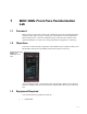
MOD 30ML Front Face Familiarization Lab 1 1.1 Foreword Many processes involve flow control loops, whether they are in the food, pharmaceutical, chemical, pulp & paper, mining or virtually any of the industries served by MODCELL Multi-loop Processors. This lab is designed to help you learn the basic features of the Application Builder, as well as how to easily demonstrate configuration of a PID loop. 1.
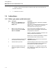
Training Manual MOD 30ML Front Face Familiarization Lab 1.4 2. 1 x Memory module (2010PZ10000A) marked FACEPLATE (and loaded with the FACEPLAT.CDB file) 3. 1 x Small flat screwdriver Instructions 1.4.1 Before you power up the instrument Step 1 Procedure Make sure the SERV/RUN switch under the front face is set to the RUN position Comments This ensures that after a download the database will be able to run. This switch is located behind the front panel in the NEMA 4 option.
Training Manual MOD 30ML Front Face Familiarization Lab 1.4.2 Operating the alarm page and power-up sequence Step 1. Procedure Comments MEM MOD will appear on line 1 WRTPROT will appear on line 2 UAK and RET will appear on lines 3 and 4 UAK = Unacknowledged alarm RET = Return to loop display (Operating) Press the Alarm Key The AUTO and MANUAL keys now function as Acknowledge and Return keys. 2. Press the Auto key UAK.
Training Manual MOD 30ML Front Face Familiarization Lab Note: Active Diagnostics An unacknowledged diagnostic condition is always indicated by flashing of the alarm LED. The indication may also include a flashing display and a beep signal depending on configuration. A dedicated alarm display provides information on all active diagnostics. An example of the display with control key information is shown in the next figure.
Training Manual MOD 30ML Front Face Familiarization Lab 1.4.3 Operating the Loop display Left Bar will display the Process variable Middle Bar will display the setpoint Right Bar will display the control output Line 1 will display the loop tag = FIC-100 Line 2 will display the process input and units = 0.
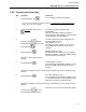
Training Manual MOD 30ML Front Face Familiarization Lab 1.4.5 Operating the Ramp keys Objective: To manually set the control output to a value of 24.8%. During the following procedure, if the time between key strokes is greater then 10 seconds, then the display will automatically change back to the operating loop display. If this is the case, simply press either the UP or DOWN key and select the character you wish to change using the FST and SLO keys. Step 1.
Training Manual MOD 30ML Front Face Familiarization Lab 1.4.6 Operating the Scroll key Step 1. Procedure Press the SCROLL key Comments Line 5 changes to display SP (Setpoint) You can use the method described in section F - OPERATING THE RAMP KEYS to change the value of the setpoint. 2. Press and hold the SCROLL key 3. twice to Press the UP key change the bottom number to 2, and then press ENT 4.
Training Manual MOD 30ML Front Face Familiarization Lab 1.4.7 Checking the Communication setup Objective: Determine the Modbus address and communication parameters of this instrument Step 1. 2. Procedure Press and hold the TAG key Comments Line 6 changes to display DEV STAT (device status). This is the start of the Status and Configuration menus. The Remote Local (R/L) and SCROLL keys now function as “previous” PRV and “next” NXT keys.
Training Manual MOD 30ML Front Face Familiarization Lab Communication Information: Modbus Address Baud Rate Stop bits Built-In Comm Enabled 1-9
Training Manual MOD 30ML Front Face Familiarization Lab Notes: 1 - 10
2 2.1 MOD 30ML Operation Lab 2 Foreword MOD 30ML can perform complex continuous control as well as discrete control. The Sequencer block in the MOD 30ML can be used for executing complex batch and sequencing control. Custom displays can be built for information and operation of the advanced control. 2.2 Objectives In this lab we will download a batch control strategy from the memory module to the MOD 30ML controller and run the batch from the custom displays.
Training Manual MOD 30ML Operation Lab 2 Figure 2 .1. Batch Temperature Cycle During the heat stage of the batch cycle, a cascade temperature loop is used to control temperature. At the time the sequence enters the heating step, the setpoint of the master controller is ramped to the reaction temperature; the master controller measures the product temperature while the slave measures jacket temperature. At the cooling stage, the setpoint is ramped back to the cool setpoint. Figure 2 .2.
Training Manual MOD 30ML Operation Lab 2 • Manual advance of sequence Initial Conditions: 1. Batch AUTO, OFF (Note: once the batch has been started, Line 2 will indicate the Time in Step for each step. If the batch is put into manual mode, Line 2 will display Manual. The “time in step” timer does not stop if the batch is put into manual. However, if you manually advance to another step, the step timer restarts). 2. RECIPE 1 selected 3. Temperature setpoint LOCAL 4. Level 0.0” H2O 5.
Training Manual MOD 30ML Operation Lab 2 2.3 Instructions 2.3.1 Download Reactor database from the memory module: Step 1 Procedure Make sure the SERV/RUN switch under the front face is set to the RUN position Comments This ensures that after a download the database will be able to run. This switch is located behind the front panel in the NEMA 4 option. You will need to remove the instrument from its housing to set it.
Training Manual MOD 30ML Operation Lab 2 2.3.2 Scroll through the displays: Step 1 Activity The first display as shown in the previous page is the main batch display. This is the display where we will start the batch. But before that, we will scroll through the other displays to get an overview. Look For Note that the batch is in AUTO mode and is not running right now (OFF). The setpoint is in local (LOC) mode. 2 Press the TAG key once to go to the TIC-100 temperature control loop display.
Training Manual MOD 30ML Operation Lab 2 You can display and manipulate on one instrument, all process and calculated values associated with the process unit, including both sequence and continuous control. 2.3.3 View the Tuning displays and change the batch recipe: 3 4 Display tuning pages for TIC-100 and TIC-101.
Training Manual MOD 30ML Operation Lab 2 2.3.4 Run the Batch: 5 Press the TAG key to return to main Batch display Press AUTO key to start the batch Batch status changes to RUN See the next figure. Setpoint status changes to REMOTE Step indication on Line 6 changes to START and then to FILL. Figure 2 .6.
Training Manual MOD 30ML Operation Lab 2 7 Return to main batch display and observe step. 8 When controller has entered HEATUP step, scroll to temperature control displays (TIC-100 and TIC101) Cascade control for temperature is now active Master controller setpoint value ramps to 111ºF. Read the process value of TIC-100. This will also ramp to 111 def F in a couple of minutes Refer to the next figure. Figure 2 .8.
Training Manual MOD 30ML Operation Lab 2 2.3.5 Switch the batch control modes: 9 When batch cycle has entered HOLD step, return to main batch display Press MAN key to put batch cycle in manual control Batch status on line 2 changes to MANUAL. STP indication appears next to Scroll key Figure 2 .9. Batch in Hold 10 Press STP key (scroll key) to scroll to COOLDOWN Press MAN key again to return batch cycle to automatic control Batch time shows on line 2.
Training Manual MOD 30ML Operation Lab 2 11 Scroll to TIC-100 display Temperature setpoint ramping down to cool setpoint 12 When batch cycle has entered DRAIN cycle, scroll to level display Falling reactor level as vessel is drained 13 Scroll back to the main display When drain cycle is finished (level has returned to 0) and current step shows as END. Press the MANUAL key, change the step to OFF, and press the AUTO key to return the batch to OFF status.
Single Loop Template Lab 3 3.1 Foreword Many processes involve flow control loops, whether they are in the food, pharmaceutical, chemical, pulp & paper, mining or virtually any of the industries served by MODCELL Multi-loop Processors. This lab is designed to help you learn simple PID loop configuration from the MOD 30ML front face. 3.
Training Manual Single Loop Template Lab 3.3 Instructions 3.3.1 Power up the controller 1. We will remove the memory module if any from the controller. Loosen 2 screws on Faceplate on controller and remove Instrument from housing. Remove Memory module from Instrument. Return Instrument to housing. Removing the memory module will prevent downloading of configuration from the memory module in case the instrument is powered up. 2. Power-up Instrument if it is not already powered up. 3.3.
Training Manual Single Loop Template Lab Figure 3 .3. MOD 30ML Alarm CLeaRed Alarm • The next figure shows an active alarm. Figure 3 .4.
Training Manual Single Loop Template Lab 3.3.3 Front face Configuration Map: The front face configuration map shows an overview of the menus available front the front oh the MOD 30ML controller. The major menu items at the top level are: These menu items can be scrolled through, by selecting NXT from the front face while DEVICE is displayed on line 1. 1. DEV STAT – This menu allows you to the following sub menus: The sub menus are reached by pressing the DOWN arrow from the main menu.
Training Manual Single Loop Template Lab 3.3.4 Scroll through the top level front face menus: Step 1 Procedure Press and hold TAG key until *DEVICE* is displayed on line 1. Comments See the figure below: 2 Press the NXT (the key next to the NXT display on the front face). 3 If you pressed any other key and do not know where you are, press and hold the TAG key until *DEVICE* is displayed at the top. See the menu items changing in line 6. 3.3.
Training Manual Single Loop Template Lab 4 Press ENT again to enter Configuration mode. You will be in DEV STAT menu mow. See the sequence of figures below: Lines 1 and 2 will display DEV STATE and INSTATE (Instrument state). Line 6 will display RUN indicating that the controller is running a valid database. 5 Press the NXT key until COMMANDS is displayed on line 2. You can issue commands to the controller from this menu. Figure 3 .6. 3-6 6 Press the DOWN key once.
Training Manual Single Loop Template Lab Figure 3 .7. 13 Acknowledge UNCONFIG alarm by pressing the ALARM key and the AUTO key. 14 Press RET key 15 If line 2 displays DEL MAIN go to Step 24 otherwise continue at step 23. 16 Press DOWN and NXT key 2 times. Press DOWN key again. Press NXT key 5 times. 17 Press NXT key The Alarm display will show INST UNCONFIG saying that the instrument is unconfigured.
Training Manual Single Loop Template Lab Figure 3 .8. 3-8 18 Press NXT key, then press the UP key You are exiting the COMMAND section 19 Press NXT key XTIMES is displayed on Line 2. Scan groups 1 through 5 are user-defined intervals for loops. The fastest group has the highest priority. The lower numbered group has a higher priority if the interval is the same. Scan group 6 is a system group. Scan groups 7 to 9 are communications groups. 20 Press NXT key TIME is displayed on Line 2. Current time.
Training Manual Single Loop Template Lab 3.3.6 System Compound – Load Defaults: 1 Press NXT until TEMPLATE is displayed on line 6. See figure below: 2 Press DOWN 3 Press DOWN LOAD DEFAULTS will be displayed on lines 1 and 2. We use the default template as a starting point for creation of a database. Default values are the basis for what is shown in the Operation manual. “VERIFY LOAD” will be displayed on lines 1 and 2 Figure 3 .9.
Training Manual Single Loop Template Lab Figure 3 .10. 3.3.7 System Compound – Edit System Template: We will change the System tag name and the system scan group 2 scan interval in this section. 1 Use the Arrow keys to scroll through INSERT, EDIT, and LIST. DO NOT PRESS ENTER INSERT is used to add a user compound after system compound.
Training Manual Single Loop Template Lab Figure 3 .11. . 7 8 Press NXT to access System Scan Groups. Press DOWN Scan groups defined update intervals for loops. SYSTEM SCANGRPS should be displayed on lines 1 and 2. See the figure above. The arrow key will change the Scan Group time by 50 mSec steps. Scan groups 1 through 5 are user defined intervals for loops Leave at 0:00.100. The fastest group has the highest priority.
Training Manual Single Loop Template Lab We will change the system tune and configuration passwords in this section. 1 Press DOWN TUNE PASSWORD is displayed on lines 1 and 2. 2 Press UP key to set 1 as password then press ENT. Enter a number required to access tuning parameters. 3 Press NXT CONFIG PASSWORD is displayed on lines 1 and 2. 4 Press UP arrow to set 2 as Configure password.
Training Manual Single Loop Template Lab Next, we will change some of the system alarm settings. 1 Press DOWN DIAGNSTC RATE is displayed on lines 1 and 2. FAST = off 100mSec, on 300 mSec. SLOW = off 250mSec, on 750mSec. We will accept the FAST rate. Alarm indication rates apply to light, display and beeper. Alarms are: unacknowledged diagnostics, high or low process and deviation conditions, and input quality 2 Press NXT DIAGNSTC FLASH is OFF. OFF = flashing is disabled.
Training Manual Single Loop Template Lab 3 - 14 9 Press NXT HIGH PRI BEEP is OFF. OFF = beeping is disabled ENABLE = beep on alarm 10 Press NXT LOW PRI RATE is SLOW. FAST = off 100mSec, on 300 mSec SLOW = off 250mSec, on 750mSec 11 Press NXT LOW PRI FLASH is OFF 12 Press NXT LOW PRI BEEP is OFF. 13 Press NXT SYSTEM appears on line 1; Lines 2 and 6 are blank 14 Press UP End of SYSTEM ALARMS 15 Press NXT End of SYSTEM functions.
Training Manual Single Loop Template Lab 3.3.8 Single Loop PID control template setup: When you loaded defaults, you automatically created a “blank” loop tag which was given the name CTAG01. We will now edit this loop. 1 Press UP arrow twice to select EDIT on line 6 and press ENT TAG ID STRING on lines 1 and 2. CTAG01 on line 6. 2 Press UP arrow to change tag characters. While display is flashing, press UP until F is displayed DO NOT PRESS ENTER 3 Press NXT .
Training Manual Single Loop Template Lab assigned. 11 Figure 3 .15.
Training Manual Single Loop Template Lab 3.3.9 Process Input Setup 1 Press NXT PROC INP will be displayed on line 2. We are entering the process input setup for our PID control loop. 2 Press DOWN This takes you into the process input definition menus. SLOT will be displayed on line 2. 3 BI 1 AIN is the default input. We will accept this. This is Built-In Analog Input 1.
Training Manual Single Loop Template Lab key to set the range at 200. Then press ENT Significant Digit to flash, indicating you can change that digit. Each time you press the FST key the flash digit will move one digit to the left. Pressing one of the arrows will cause the flashing digit to ramp up or down. Press NXT EU LABEL will be displayed on line 2. 13 Using the UP/DOWN keys and NXT key, spell out GPM Then press ENT Up to a 4 character label to appear after process input value.
Training Manual Single Loop Template Lab 16 Press NXT 17 Set line 6 at 220. Then press ENT 18 Press NXT until line 2 and 6 are blank and only the up arrow is on 19 Press UP 20 Press NXT HI QUAL is displayed on line 2. Result is set BAD if it goes above this value. High quality must be higher than the low quality value This completes the Process Input section. SETPT will be displayed on line 2. Figure 3 .19.
Training Manual Single Loop Template Lab 3.3.10 SETPOINT Setup 1 Press DOWN to enter setpoint section. 2 Press NXT until SETPOINT HI LIMIT is displayed on lines 1 and 2. 3 Set the high limit at 200. press ENT. 4 Press NXT until INITIAL VALUE is displayed. 5 Set the value at 100.0. Then press ENT. Setpoint value when configuration is complete. 6 Press NXT until lines 2 and 6 are blank and only the up arrow is on.
Training Manual Single Loop Template Lab 3.3.11 CONTROL Setup 1 Press DOWN to enter control section. This takes you down into the Control menus 2 ALGO TYP is displayed on line 1. Gain (1st Character): What is the ALGO TYPE ? O = Off P = On Process E = On Error Reset (2nd Character): O = Off S = Standard M = Micro-Scan Pre-Act (3rd Character): O = Off P = On Process E = On Error Manual Reset (4th Character): O = Off E = Enabled Figure 3 .21. Figure 3 .22.
Training Manual Single Loop Template Lab 3 - 22 3 Press NXT until “GAIN” is displayed on line 1. Set Gain at 0.65. Then press ENT. 0.01 to 125.0 Proportional response in a fixed gain controller. 4 Press NXT, set Reset at 30.00 then press ENT 0.01 to 125.0 Reset in repeats per minute. 5 Press NXT until INITIAL MODE is displayed on lines 1 and 2. 6 Set Mode to AUTO. Then press ENT 7 Press NXT until lines 2 and 6 are blank and only the up arrow is on.
Training Manual Single Loop Template Lab 3.3.12 OUTPUT Setup 1 Press DOWN to enter output section 2 Leave the default value of BI1 AOUT in place 3 Press NXT 4 Press NXT NONE, BI1 AOUT, BI2 AOUT, and S01 to S11. Only available outputs are listed. OUTPUT LO SIGNL displayed. 0% of the output range. OUTPUT HI SIGNL displayed. 100% of the output range Figure 3 .23. 5 Press NXT until OUTPUT LO LIMIT displayed 6 Set limit to 0.0.
Training Manual Single Loop Template Lab Figure 3 .24. 3 - 24 8 Set limit to 100.0 and press ENT 9 Press NXT until Line 2 displays OUTPUT INIT VAL 10 Change the initial value to 50 11 Press NXT until COMPOUND is displayed on line 1 12 Press UP This completes the output section. 13 Press NXT This takes you to the ALARM section of the configuration tree. We will not setup any process alarm in this lab. 14 Press NXT COMPOUND is displayed on line 1 and LIST on line 2.
Training Manual Single Loop Template Lab 3.3.13 Install the edited template 1 Press UP CMP LIST and 2. FIC 100 is displayed on lines 1 2 Press NXT CMP LIST is displayed on line 1; lines 2 and 6 are blank 3 Press UP EDIT TEMPLATE displayed on lines 1 and 2. 4 Press NXT INSTALL TEMPLATE displayed 5 Press DOWN. Select INITWARM INSTALL TYPE displayed. 6 Press ENT This compiles your configuration and loads it into runtime memory. You should now see the FIC-100 display.
Training Manual Single Loop Template Lab 3 - 26
4 4.1 MOD 30ML Diagnostics Lab Foreword The MOD 30ML provides a comprehensive way of displaying active diagnostic information as well as a history of events. Events are a combination of alarms and information only activities that the instrument had gone through. 4.2 Objectives We learnt how to read the active diagnostics and acknowledge them in Chapter1. In this lab we will read the diagnostics history by using the Event Viewer available from the front-face.
Training Manual MOD 30ML Diagnostics Lab 4.4 Instructions 4.4.1 Event Viewer The System Event block stores diagnostics reported by the data base blocks. Viewing the system event queue provides data on all diagnostics that have occurred since the current data base was down loaded or the queue was cleared. The queue contains both informational and diagnostic data. The data for each event in the queue is displayed on two pages. View the data in the event queue using the following procedure: .
Training Manual MOD 30ML Diagnostics Lab page1 6 Press NXT to display the next event in the queue. Page 1 of the next event will be displayed next. 7 Use the block type and event code, to locate the event description and recommended action listed in Section 7.3. Pressing the DOWN arrow will display the time at which the event occurred and line 6 will display the nature of this event – in this example, the “INST IN RUN” is the event and it means that the instrument was put in RUN mode.
Training Manual MOD 30ML Diagnostics Lab 4.3.2 To clear events form the event history: The controller can store up to a maximum of 1000 events in its queue. The default queue size is 50 events and is configured in the SE (System Event) block of the database. You can configure what goes in to the queue. By default, the following are entered in the event list: (see the next figure) 1. 2. 3. 4. 5. 6.
Training Manual MOD 30ML Diagnostics Lab 2 Press DOWN key once. If PASSWORD is not displayed on line 2, go to step 5. Otherwise continue with Step 3. 3 Use UP key three times to select the PASSWORD and then use ENT to enter. See the next set of figures Lines 1 and 2 will display CURRENT LEVEL and Line 6 will display CONFIG indicating that the controller is in configuration mode. 4 Press ENT again to enter Configuration mode. Lines 1 and 2 will display DEV STATE and INSTATE (Instrument state).
Training Manual MOD 30ML Diagnostics Lab 4-6 6 Press the DOWN key once. CLR Q is displayed on line 2. 7 Press the UP arrow. YES will be displayed. 8 Press ENT (SCROLL key). The Events queue will be cleared and line 6 will display NO again. 9 Press the TAG key. The DEVICE page will be displayed. 10 Pres the TAG key again. Your runtime display will be displayed.
Training Manual MOD 30ML Diagnostics Lab 4.5 Instrument Shutdown 4.5.1 Force a shutdown Step 1 Procedure Make sure the SERV/RUN switch under the front face is set to the RUN position Comments This ensures that after a download the database will be able to run. This switch is located behind the front panel in the NEMA 4 option. You will need to remove the instrument from its housing to set it.
Training Manual MOD 30ML Diagnostics Lab 4-8 7 Press the SCROLL key ONCE. The PID setpoint will be shown on line 6 and the text “SP” on line 5. 8. Press the SCROLL key one more time and wait for a few seconds. The runtime PID display will disappear and FAILURE will be displayed on line 1 with an audible continuous alarm. At this point, you cannot operate the PID loop or use the controller. This is an indication that the controller is in SHUTDOWN mode.
Training Manual MOD 30ML Diagnostics Lab 4.5.2 Read the shutdown information and acknowledge it: Step 1 Procedure The first step in reading the shutdown info is to cycle power the controller. Power down the controller and then power it. Comments After power up the DEVICE display will come up. The instrument will be in default mode and Line 3 will display DEF as shown in the first figure below. There will be diagnostic alarms and the RED LED will be flashing.
Training Manual MOD 30ML Diagnostics Lab 3 Press the TAG button after viewing and acknowledging the alarms. The instrument will display the DEVICE display. Line 6 will show DEV STAT. See the middle picture in the next figure. 4 Press the DOWN arrow to enter the DEV STAT menu. The first page in this menu shows the Instrument’s state as shown in the last picture in the next figure. The device state is DEFAULT after a SHUTDOWN. 5 Press the NXT to view the SHUTDOWN page.
Training Manual MOD 30ML Diagnostics Lab 7 Press the NXT key to view Pages1, 2 3 and 4 and record the information Shutdown page 2 displays the time and date of the shutdown. 8 Press NXT to go to Page 5 Page 5 displays ACK SD and NO on lines 2 and 6 respectively. See the next figure: Press the UP/DOWN arrow to show YES on line 6 and then press the key next to EXT on the display This will acknowledge the Shutdown and line 6 will display NO again. Line 3 will now change to display RUN.
Training Manual MOD 30ML Diagnostics Lab Notes: 4 - 12
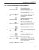
Touring The MOD 30ML Front Face Configuration Menus Front Face Configuration Map
This Page Left Intentionally Blank
A2_FrontFace_Config.ppt See Page 2 DEV STAST ANY TAG SETUP PASSWORD Change Access level PASSWORD Password entry CURRENT LEVEL NONE Current access level SETUP *DEVICE* BI MSC 1 ENABLED Built-in MSC 1 enabled BI COMM SETUP Built-in Commn. BI MSC 1 BAUDRATE Built-in MSC 1 Baudrate BI MSC 1 PARITY Built-in MSC 1 parity BI MSC 1 STOPBITS Built-in MSC 1 stop bits BI ICN 1 ENABLED Built-in ICN enabled BI MSC 1 ADDRESS Built-in MSC 1 address SETUP BI COMM Built-in Commn.
This Page Left Intentionally Blank
A2_FrontFace_Config.
This Page Left Intentionally Blank
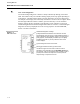
LIST ENT EDIT NEXT SCAN GROUP 5 Scan group 5 interval SYSTEM SYSTEM PASWORDS System passwords TUNE PASSWORD Setup tune password CONFIG PASSWORD Setup config password ACCESS TIMEOUT Access timeout SYSTEM SYSTEM ALARMS System alarms DIAGNSTC RATE Diagnostic rate DIAGNSTC FLASH Diagnostic Flash SYSTEM DEV TAG System device tag SYSTEM SCANGRPS System scan groups SCAN GROUP 1 Scan group 1 interval INSERT (System compound) CMP LIST SYSTEM A2_FrontFace_Config.
This Page Left Intentionally Blank
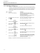
CMP TYPE A2_FrontFace_Config.
This Page Left Intentionally Blank
A2_FrontFace_Config.
The Company’s policy is one of continuous product improvement and the right is reserved to modify the information contained herein without notice, or to make engineering refinements that may not be reflected in this bulletin. Micromod Automation assumes no responsibility for errors that may appear in this manual. © 2004 MicroMod Automation, Inc. Printed in USA IB-MLOPR-TUT, Issue 3 MicroMod Automation, Inc. 75 Town Centre Drive Rochester, NY USA 14623 Tel. 585-321 9200 Fax 585-321 9291 www.