
Maintenance for 2001N, 2002N, and 1800R Manual

MOD30ML and Modcell Maintenance Manual
DIAGNOSING I/O MODULE PROBLEMS
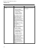
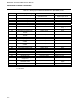
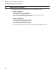
Table 5 .1. I/O Module Identification Codes
Module Type
Catalog No. ID Code
Voltage Input 2001A $FE0000
Current Input 2002A $FE0100
Current Input with 2-wire
transmitter power
2012A $FE0400
Thermocouple 2013A $FE0200
Cold Junction comp.(CJC) 2010A $FE0300
RTD, 2-wire 2009A $FE0500
RTD, 3-wire 2009A $FE0600
Analog Output 2003N $FD0500
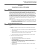
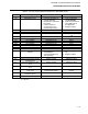
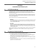
3. Read the extended error from the module as follows:
• Type the following:
R (module)(x),EXTERR
where (module) and (x) are the same as in Step 2 For example, to read the extended
error for occurrence number 1 of a WRIM module, type:
R WRIM1,EXTERR
• Observe the data returned. An example of the data for a WRIM module with a fault is
shown in Figure 5.1. The decimal error code number, 14368, is converted to a 16-bit
binary number in which one group of bits provide status information and the second
group indicates errors. The software converts the decimal code and groups the
information as Status bits and Error Bits as shown in Figure 5.1.
4. Refer to Section 5.3 for information on interpreting the error code data.
Figure 5 .1. Example of Extended Error Code Data for a WRIM Module
5 -2