
Maintenance for 2001N, 2002N, and 1800R Manual

Technical Notice
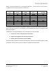
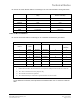
Pin outs for the 1753F RS-232 cable for connecting PC to 1720 Communication Link is given below:
Color Pin no. (25 pin connector on the PC
side)
Pin no. (25 pin connector on the
Comm. Link side)
BLACK 1 GND 1 GND
BLACK 2 Tx 3 Rx
BLACK 3 Rx 2 Tx
GREEN 4 RTS 5 CTS
WHITE 5 CTS 4 RTS
RED 7 Common 7 Common
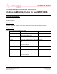
Cables for Mini Link External
Pin outs for the RS-232 cable for connecting PC to 1733N Mini Link External is given below:
PC side Mini Link External Side
25 Pin port -
DB25f
9 Pin port
- DB9f
Function Function 9 Pin port- DB9m 25 Pin port
–
DB 25m
1 Shell Ground Ground 1 1
2 3 Tx Data Rx Data 2 2
3 2 Rx Data Tx Data 3 3
7 5 Common Common 5 7
6 6 DSR RTS 7 4
20 4 DTR CTS 8 5
+5 Vdc 9
Notes:
1. DSR-RTS and DTR-CTS connections are not required if Jumpers W16 and W17 are removed.
2. The +5Vdc connection is for test purposes only.
3. The Ground connections are optional.
4. The cable shield may be connected to ground at either end, but not both.
For the latest list of technotes, visit http://www.micromodautomation.com or contact us at 585 321
9200
Topic: MOD 30ML/Modcell Technote: TNML0702-1
MicroMod Automation, Inc. Rev. July-2002
Comm Cables.doc Page 3 of 4