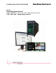
Continuous Control Functions Data Base Reference BOOK 3: PID and Ramp/Soak Functions for 2004P - MODCELL™ Continuous Control Identity Module (Version 3) 1800P - MOD 30ML™ Identity Module (Version 2)
MicroMod Automation, Inc. The Company MicroMod Automation is dedicated to improving customer efficiency by providing the most cost-effective, application-specific process solutions available. We are a highly responsive, application-focused company with years of expertise in control systems design and implementation. We are committed to teamwork, high quality manufacturing, advanced technology and unrivaled service and support.
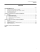
Continuous Control Functions CONTENTS CONTENTS Page SECTION 1 - INTRODUCTION 1.1 GENERAL .......................................................................................................................................... 1-1 1.2 OVERVIEW OF INSTRUMENT SOFTWARE.................................................................................... 1-1 1.3 DATABASE CONFIGURATION AND RUNTIME SUPPORT ............................................................ 1-1 1.4 RELATED DOCUMENTATION..................
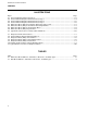
Continuous Control Functions CONTENTS ILLUSTRATIONS Figure Page 2-1. Overview Diagram, PID Control Block ..................................................................................................... 2-3 2-2. Functional Block Diagram, PID Control Block, Page 1 ............................................................................ 2-4 2-2. Functional Block Diagram, PID Control Block, Page 2 ............................................................................ 2-5 2-2.
Continuous Control Functions INTRODUCTION 1 INTRODUCTION 1.1 GENERAL This document includes database reference information to aid in configuring a MOD 30ML Controller or a MODCELL Multiloop Processor with regulatory controller software. Information on database organization, database memory block structures and the logic control portion of this controller is described in IB-23G600.
Continuous Control Functions INTRODUCTION 1.4 RELATED DOCUMENTATION Additional information about logic and display functions can be found in: • IB-23G600 – Database Reference for Logic Functions - Book 1 • IB-23G602 – Database Reference for Logic Functions - Book 2 • IB-1800R-APP – Database Reference for MOD 30ML Functions Information about configuration of the functions in this book can be found in: • ViZapp.
Continuous Control Functions PID CONTROL BLOCK 2 PID CONTROL BLOCK DATABASE PARAMETERS 2.1 GENERAL This section includes database reference information for the PID Control block. For information on environmental, communications, and I/O block parameters, see IB-23G600. This reference information includes attribute definition, block capabilities, and examples of usage. The information is intended to aid the user in understanding and configuring the instrument database.
Continuous Control Functions PID CONTROL BLOCK 2.2 PID CONTROL BLOCK (PID) Regulatory control is supported through use of the PID Control block. The basic functions of each PID block include: • Basic PID Control (Gain, Reset, Pre-Act) algorithms.
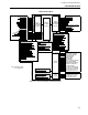
Continuous Control Functions PID CONTROL BLOCK PID Controller Block Process Value Remote Setpoint Remote Ratio Remote Bias Setpoint Selector A Setpoint Selector B Output Selector A Output Selector B Track Command Output Track Setpoint Track Output Restart Setpoint Restart External Feedback Deadtime Compensation Feedforward Compensation Gain Modifier Reset Modifier Preact Modifier Input Conditioning (See Figure 2-2 page 1) Setpoint Modes Allowed Setpoint Mode Restart Setpoint Mode Command Setpoint Track E
Continuous Control Functions PID CONTROL BLOCK + ADJUSTED REMOTE SETPOINT / Sum - Remote Setpoint Bias Input (None, LSP, FP Value) AUTO RATIO STANDARD BIAS AUTO BIAS Setpoint Auto Balance Remote Setpoint Balance Type AUTO RATIO RATIO STANDARD Remote Setpoint Ratio Input (None, LSP, FP Value) AUTO BIAS Top Remote Setpoint Input (None, LSP, FP Value) Bottom Remote Setpoint Range Top Bottom Process Variable Range X Sum Setpoint Selector A Input (None, LSP, FP Value) Selector Logic Setpoi
Continuous Control Functions PID CONTROL BLOCK Output Manual Reset Balance Type (None, Procedureless) Balance Calculation Error Output Mode MANUAL RESET VALUE Output Range RESET Base Value Reset Modifier (None, LSP, FP Value) External Feedback (standard reset) X Output Range GAIN Base Value PID Algorithm Gain Modifier (None, LSP, FP Value) (Auto or Cascade Mode - see block operation description) X or Microscan Feedback Output Range PREACT Base Value Preact Modifier (None, LSP, FP Value) X Fe
Continuous Control Functions PID CONTROL BLOCK Control Mode Restart (MANUAL, AUTO, CASCADE, PREVIOUS, N/A) Control Mode Logic Control Modes Allowed (M, A, A.M, C, M.C, A.C, M.A.
Continuous Control Functions PID CONTROL BLOCK Figure 2-3. PID Control Block (PID), General Menu with Tuning Value Setup Figure 2-4.
Continuous Control Functions PID CONTROL BLOCK Figure 2-5. PID Control Block (PID), Controller Mode Menu Figure 2-6.
Continuous Control Functions PID CONTROL BLOCK 2.2.1 PID Control Block Operation The PID calculation is performed provided that the mode is AUTO or CASCADE, and that all required inputs are available and GOOD. The algorithm types that drive the PID calculation are proportional on error or process, standard or MICRO-SCAN integral or manual reset, PreAct on error or process.
Continuous Control Functions PID CONTROL BLOCK Setpoint high/low limits and output high/low limits cannot be written such that the limit values invert; that is, the high value cannot be set less than the low value. Quality Checks If the track command input quality is bad (Bad Inputs Accepted = NO), the PID block is unable to determine what mode it should be in. It therefore sets the output mode (and controller mode, if configured) to FAULT.
Continuous Control Functions PID CONTROL BLOCK Error Checks If a calculation error occurs in the PID calculation, and the set qualities bad attribute is TRUE, then the output qualities (output and track status) are set BAD. The PID calculation will be initialized when qualities become good again.
Continuous Control Functions PID CONTROL BLOCK Table 2-1.
Continuous Control Functions PID CONTROL BLOCK Table 2-1.
Continuous Control Functions PID CONTROL BLOCK Table 2-1. PID Control Block Attributes, Valid Values, Mnemonics, and Data Types (Cont’d) Field Name / Attribute Track Command Input Setpoint Track Input Output Track Input Mnemonic Valid Values TCI NONE, discrete value, or LSP SPTI NONE, Floating Pt. Value, or LSP OPTI NONE, Floating Pt. Value, or LSP PRMI NONE, Positive Floating Pt.
Continuous Control Functions PID CONTROL BLOCK 02 03 04 Block State (STATE) ..........................................................................................................CWR All block state changes are reported as informational events. See IB-23G600 Section 2.4.1, State Changes for additional information. RUN 0 Normal Operation. Block is executed. HOLD 1 Block is not executed. Qualities retain previous values. OFF 2 Block is not executed. Qualities will be BAD.
Continuous Control Functions PID CONTROL BLOCK 08 09 10 11 12 13 14 2-16 Calculation Error Active (CERRA) ...................................................................................– WR If the calculation error diagnostic is enabled, the active status indicates if the diagnostic is active even after acknowledgement. Only writeable in DEBUG. NO 0 Diagnostic error is not active. YES 1 Diagnostic error is active. Calculation Error Active Quality (CERRAQ) .................................
Continuous Control Functions PID CONTROL BLOCK 15 16 17 18 Control Interval (CI) ...........................................................................................................CWR The control interval is a millisecond time value that represents the number of milliseconds between executions of a PID control algorithm within a block. 0 run PID algorithm at whatever rate block runs (determined by loop rate).
Continuous Control Functions PID CONTROL BLOCK 19 20 Setpoint Mode Command (SPMC)................................................................................... – – R The setpoint mode command represents value to which setpoint mode will return when TRACK clears. If you are in Track and want to return to a control mode other than the value indicated here, you must write to the Controller Mode (CMS) whose value will then be reflected here. LOCAL 0 Setpoint returns to Local when track clears.
Continuous Control Functions PID CONTROL BLOCK 25 Remote Setpoint Range Top (RSPRH) ............................................................................CWR The remote setpoint range high floating-point value represents the top of the setpoint range and must be greater than the range low value. The remote setpoint range values are used to scale the remote setpoint input from setpoint units to input units.
Continuous Control Functions PID CONTROL BLOCK 31 Remote Setpoint Balance Type (SPBTYPE) ...................................................................C – R Transfers to remote setpoint can be made bumpless by specifying auto ratio or auto bias. Transfers to local are always bumpless as the local setpoint signal is maintained at the active setpoint when not in local. AUTO RATIO or AUTO BIAS cannot be used if the corresponding remote input is configured.
Continuous Control Functions PID CONTROL BLOCK 38 Deviation (DEV)................................................................................................................CWR This is the normalized deviation output (process input minus active setpoint). 39 Deviation Quality (DEVQ)................................................................................................. – WR Deviation quality is based on the process and setpoint qualities.
Continuous Control Functions PID CONTROL BLOCK 44 Unlimited Output (UOP)....................................................................................................– WR The unlimited output is the PID floating point output before limits are applied. This value is initialized from the output value. 45 Unlimited Output Quality (UOPQ) ...................................................................................– WR The unlimited output quality depends on any block input and its quality.
Continuous Control Functions PID CONTROL BLOCK 53 54 55 56 Output Modes Limited (OPML)........................................................................................ C – R The output modes limited count value is used to limit the output modes to those selected. A 2 Output modes are limited to AUTO. M.A 3 also A.M. Output modes are limited to MANUAL and AUTO. A.T 6 also T.A. Output modes are limited to AUTO and TRACK. M.A.T 7 Also T.A.M, T.M.A, A.T.M, A.M.T, M.T.A.
Continuous Control Functions PID CONTROL BLOCK 59 Control Algorithm Type (CATYPE) .................................................................................C – R This line specifies the types of control actions for the controller. The valid actions and their values are described below. Gain (column 1): O 0 Off. Gain response is turned off. P 1 On Process. Gain response value is determined by process input signal. E 2 On Error. Gain response value is determined by error signal.
Continuous Control Functions PID CONTROL BLOCK The valid entries and their long state values are: 60 EOOO OSOO PSOO ESOO OMOO PMOO EMOO EOPO PSPO 2 4 5 6 8 9 10 18 21 ESPO PMPO 22 25 EMPO 26 EOEO ESEO EMEO 34 38 42 EOOE EOPE EOEE 66 82 98 Gain on error, Reset off, Pre-Act off, manual reset off. Gain off, standard Reset, Pre-Act off, manual reset off. Gain on process, standard Reset, Pre-Act off, manual reset off. Gain on error, standard Reset, Pre-Act off, manual reset off.
Continuous Control Functions PID CONTROL BLOCK 63 Preact Time Base Value (BPREACT) ............................................................................... CWR The preact time base value can be any floating-point value in the range of 0.07 to 32.0 minutes. This derivative time filter is typically used on temperature inputs that have smooth changes and lags and not on flow signals that are typically noisy and have no lags. OFF Preact Time Base Value is 0.0. Preact response is off.
Continuous Control Functions PID CONTROL BLOCK 67 Control Mode (CMS) ..........................................................................................................CWR This is the active controller mode. The controller mode can be represented as a separate output and setpoint mode, or singly as a controller mode. If controller mode is used, the following conditions are checked: • A remote setpoint source must be configured • Allowed output modes and allowed setpoint are set to M.A and L.
Continuous Control Functions PID CONTROL BLOCK 70 71 72 75 76 2-28 Setpoint Mode Restart Value (SPMRV) ........................................................................... CWR The setpoint mode restart value is used when the instrument is initialized due to a cold of frozen restart. Restart mode values must not conflict with the allowed modes value. LOCAL 0 The setpoint mode restart value is LOCAL. REMOTE 1 The setpoint mode restart value is REMOTE.
Continuous Control Functions PID CONTROL BLOCK 77 78 79 80 81 82 Setpoint Restart Value (SPRVI) ........................................................................................CWR The setpoint restart value is a floating-point input used to determine the active setpoint when the PID block performs its first RUN cycle. NONE Attribute is not configured into the database. value Fixed floating point value is Setpoint Restart value. LSP Any floating-point variable is Setpoint Restart value.
Continuous Control Functions PID CONTROL BLOCK 83 84 85 86 87 2-30 Gain Modifier Proportional Response Input (PRMI) .......................................................... CWR The gain modifier input is used when the proportional gain needs to be modified as a result of process changes. The Base Gain Value (BGAIN) is multiplied by the Gain Modifier to produce the actual proportional gain used in the PID algorithm. To input a specific value, the Base Gain Value must be set at 1.0.
Continuous Control Functions PID CONTROL BLOCK 88 89 90 91 92 93 Remote Setpoint Input (RSPI) ..........................................................................................CWR When the setpoint mode is REMOTE, the active setpoint is the remote setpoint value multiplied by the ratio and added to the bias. NONE Attribute is not configured into the database. value Fixed floating point value is Remote Setpoint Input value. LSP Any floating-point variable is Remote Setpoint Input value.
Continuous Control Functions PID CONTROL BLOCK 94 Mode Model (MM) ..............................................................................................................C – R The mode model specifies whether Output and Setpoint Mode are manipulated independently, or in combination as subordinate to the Controller Mode attribute. The mode model states are: SP/OP MODE 0 Setpoint/Output Mode. CTRL MODE Controller Mode. A Remote Setpoint Input must also be configured.
Continuous Control Functions PID CONTROL BLOCK Input Filter Time Constant (FILTIME)...............................................................................CWR The filter time in minutes (floating point value) when USER is specified as the filter type. Otherwise, it is 0.0. 101 value Any floating-point value in minutes where 0.0 = no filtering (last sampled value is the input value) 1.0 = a 1 minute 1000.
Continuous Control Functions PID CONTROL BLOCK 2.2.4 PID Block Events The event codes (and their suggested text messages) for the PID block are given below. See the referenced database attributes (in brackets) for additional information. See System Event Block, Logic Functions - Book 1, IB-23G600 for event transition information.
Continuous Control Functions RAMP SOAK BLOCK 3 RAMP SOAK BLOCK (RSK) DATA BASE PARAMETERS 3.1 GENERAL The Ramp/Soak profile block can have up to 36 ramp or soak segments. The ramp function changes the block result (setpoint) up or down at a linear rate over the specified period of time. The soak function maintains the block result at a fixed value for the specified period of time. A step function has a specified time of zero.
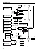
Continuous Control Functions RAMP SOAK BLOCK Command or Input Value: RUN or RESET = RUN STOP or HOLD = HOLD Discrete LSP Discrete Value Track Command Input FP LSP Mode Logic Startup Type START GOOD Track Input TRACK BAD FP LSP Repeat PROCESS GOOD Process Input Fp Value Restart Mode (RUN, HOLD, PREV) TRUE = TRACK Start Value Fp Value Return Mode (RUN, HOLD) Ramp Hysteresis Command MODE Soak Hysteresis BAD R Discrete LSP GOOD Skip Input Discrete Value SA SB BAD Discrete LSP Discr
Continuous Control Functions RAMP SOAK BLOCK 3.2 RAMP/SOAK BLOCK OPERATION Figure 3-1 shows the characteristics of a Ramp/Soak profile. Explanations of the profile characteristics follow. Initial values are written to this block when it is initially downloaded. They may be overwritten when this block executes. PROFILE STARTUP Segment 1 may start with a Step, a Soak or a Ramp as follows: • Segment 1 starts as a step segment if the time interval for segment 1 is 0.
Continuous Control Functions RAMP SOAK BLOCK REPEAT The repeat function permits the ramp/soak profile to be repeated automatically without operator intervention (YES). No repeat means that when the profile completes the last segment the Result and States A through D will remain unchanged. The Active Segment Number (ACTSEG) will be set to zero. The profile can be restarted by a Reset or Stop command or by writing to the Active Segment Number attribute.
Continuous Control Functions RAMP SOAK BLOCK HOLD The mode can be changed to Hold by the Hold Input, by way of the Command attribute or by writing to the Mode Status attribute. RUN The mode can be changed to Run by the Run Input, by way of the Command attribute or by writing to the Mode Status attribute. STOP A Stop can be initiated by the Stop Input or by way of the Command attribute. Initiating a Stop will set the profile to segment 1, Cycle Count to 1 and the Mode to hold.
Continuous Control Functions RAMP SOAK BLOCK Figure 3-3. Ramp/Soak Block (RSK), General Menu Figure 3-4.
Continuous Control Functions RAMP SOAK BLOCK Figure 3-5. Ramp/Soak Block (RSK), Restart Menu Figure 3-6.
Continuous Control Functions RAMP SOAK BLOCK Table 3-1. RSK Block Attributes, Valid Values, Mnemonics, and Data Types Field Name Version Block Length State Bad Inputs Repeat Profile Use Output States Startup Type Restart Mode Restart Segment Mnemonic VERSION BLKLEN STATE BADINP REPEAT USE STYPE RUN (0), HOLD (1), OFF (2), DEBUG (3). REJECTED (0), ACCEPTED (1). NO (0), YES (1). Default is NO NO (0), YES (1). Default is NO START VALUE (0) - Default is START.
Continuous Control Functions RAMP SOAK BLOCK Field Name Mode Mode Quality Return Mode Bad Track Input Process Input Track Input Track Command Input Reset Input Stop Input Run Input Hold Input Skip Input Segment 1 Target Value ...etc 2 through 35 Segment 36 Target Value Segment 1 Time Interval ...etc 2 through 35 Segment 36 Time Interval Segment 1 Guaranteed ...etc 2 through 35 Segment 36 Guaranteed Segment 1 State A ...etc 2 through 35 Segment 36 State A Segment 1 State B ...
Continuous Control Functions RAMP SOAK BLOCK Block Type RSK This is the Ramp/Soak type. Block type code is 56. 00 Version (VERSION) ........................................................................................................... – – R The RSK block is at version 1. 01 Block Length (BLKLEN) .................................................................................................... – – R Number of data base bytes used by this block.
Continuous Control Functions RAMP SOAK BLOCK 04 05 06 07 Repeat Profile (REPEAT)...................................................................................................CWR Repeat profile allows the whole ramp/soak profile to be repeated (YES). If NO, the ramp/soak cycle will stop after the last segment. NO 0 Stop ramp/soak cycle after last segment. Default is NO. When the profile completes the last segment the Result and States A through D will remain unchanged.
Continuous Control Functions RAMP SOAK BLOCK 08 Restart Segment (RESSEG) ............................................................................................. CWR Restart Segment determines the segment to use on a cold instrument restart. On a warm instrument restart, the block will resume at the segment that was active before the restart. PRESET 0 Indicates an inactive profile. PRESET 1 - 36 Restarts at the beginning of the specified segment number.
Continuous Control Functions RAMP SOAK BLOCK 15 Result Quality (RQ)............................................................................................................. -WR Quality of Result when Bad Inputs are REJECTED. GOOD 0 If all of the inputs are good, then the ramp soak block updates the Result and the quality is set good. If bad inputs are accepted, then the Result Quality is set good.
Continuous Control Functions RAMP SOAK BLOCK 22 State D (SD) ....................................................................................................................... CWR This value will be the status of State D for the current segment. 23 State D Quality (SDQ) .........................................................................................................-WR Quality of State D when Bad Inputs are REJECTED.
Continuous Control Functions RAMP SOAK BLOCK 28 Cycle Number (CYCNUM) .................................................................................................CWR Indicates the active cycle the profile is currently running in. This number starts at one and is reset to one when the profile is reset. The cycle number stops counting once the number reaches 65535. 29 Cycle Number Quality (CYCNUMQ) ..................................................................................
Continuous Control Functions RAMP SOAK BLOCK 33 Bad Track Input (BADTRK) ............................................................................................... CWR See Section 2.3.2, Data Quality for additional information. REJECTED 0 The track input quality is checked if Bad Track Input Accepted attribute is False. If it is False and the track input quality is bad, then the ramp soak block does not update its outputs and the output qualities are set bad.
Continuous Control Functions RAMP SOAK BLOCK 38 Stop Input (STOPINP)........................................................................................................CWR A FALSE to TRUE transition resets the profile to segment 1 and the mode to HOLD. NONE local data No Stop input configured. Attribute is not used. 0 source pointer 39 Any discrete source. Run Input (RUNINP)...........................................................................................................
Continuous Control Functions RAMP SOAK BLOCK 201 Segment 1 Time Interval (TIS1)........................................................................................ CWR Time that this segment will take to execute. Default value is 0. The Ramp Rate is determined from the Time Interval and the difference between the Start Value and the first Target Value or between Target Values. SOAK is displayed when Target Values are the same. STEP is displayed if the Time Interval is zero.
Continuous Control Functions RAMP SOAK BLOCK 501 Segment 1 State B (SBS1) ................................................................................................CWR Status of State B during segment. FALSE 0 A blank box indicates State B for this segment is FALSE. Default is FALSE. TRUE 1 An X in the box indicates State B for this segment is TRUE. ... ...etc 2 through 35 600 Segment 36 State B (SBS36) ........................................................................................
Continuous Control Functions RAMP SOAK BLOCK 3.4 TYPICAL BLOCK CONNECTIONS FOR RAMP/SOAK BLOCK A typical Ramp/Soak Profile is used as the Remote Setpoint to the PID block. Whenever the PID block Output Mode is not AUTO or the Setpoint Mode is LOCAL the PID block Track Status is set TRUE. Therefore, the Ramp Soak block will go to the TRACKING state. Connections between the Ramp Soak block and the PID block are shown in Figure 3-7.
Continuous Control Functions PID BLOCK CROSS REFERENCE APPENDIX A PID BLOCK CROSS REFERENCE A.1 GENERAL Table A-1 list all the PID attributes by their field name. Table A-1.
Continuous Control Functions PID BLOCK CROSS REFERENCE Field Name Mnemonic Attr Input Filter Time Constant FILTIME 101 Input Filter Type FILTYPE 100 MRBTYPE 60 MR 64 MRQ 65 Mode Model MM 94 Output OP 46 OPCERRA 13 OPCERRAQ 14 OPCERRU 11 OPCERRUQ 12 OPCERRS 10 Output Limit High OPLH 50 Output Limit Low OPLL 51 Output Mode Command OPMC 43 Output Mode Restart Value OPMRV 71 Output Mode Status Quality OPMSQ 42 Output Mode Status, Initial Value OPMS 41 Output Mod
Continuous Control Functions PID BLOCK CROSS REFERENCE Field Name Mnemonic Attr Remote Setpoint Range High RSPRH 25 Remote Setpoint Range Low RSPRL 26 Remote Setpoint Ratio Input RSPRI 86 Remote Setpoint Ratio Quality RSPRQ 33 RSPR 32 BRESET 62 Reset Rate Modifier Integral Response Input IRMI 84 Setpoint Limit High SPLH 27 Setpoint Limit Low SPLL 28 Setpoint Mode Command SPMC 19 Setpoint Mode Restart Value SPMRV 70 Setpoint Mode Status Quality SPMSQ 18 Setpoint Mode Sta
Continuous Control Functions PID BLOCK CROSS REFERENCE A-4
Continuous Control Functions INDEX A ACTSEG 3-8, 3-9, 3-13, 3-16 ACTSEGQ 3-8, 3-9, 3-16 adaptive gain, reset 2-25_2-27 ALARMINP 2-35 anti-reset windup 2-25 ARSP 2-12, 2-19 ARSPQ 2-12, 2-19 attribute 1-1 B BADINP 3-8, 3-12 BADTRK 3-10, 3-18 BGAIN 2-14, 2-26, 2-31 BLKLEN 2-11 BLKLEN 3-8, 3-12 BPREACT 2-14, 2-27, 2-31 BRESET 2-14, 2-27, 2-31 bumpless 2-21_2-22, 2-26 C cascade 2-2, 2-5, 2-9, 2-14, 2-22, 2-27, 2-33 CATYPE 2-13, 2-25 CERRA 2-11, 2-17 CERRACT 2-13, 2-25 CERRAQ 2-11, 2-17 CERRS 2-11, 2-16 CERRU 2-
Continuous Control Functions INDEX H HOLDINP 3-11, 3-12, 3-19 I ICN 1-1_1-2 Identity Module 1-2 initialization 2-11 IRMI 2-15, 2-31 L lags 2-27 Limiting 2-2 logic control 1-1 LSP 2-1 M MICRO-SCAN 2-2, 2-9, 2-25 Modbus 1-1_1-2 MODE 3-5, 3-10, 3-17 MODEQ 3-10, 3-17 MR 2-14, 2-27 MRBTYPE 2-14, 2-26 MRQ 2-14, 2-27 N NUMSEG 3-8, 3-14 O OMOO 2-5, 2-13, 2-26 OP 2-3, 2-6, 2-13, 2-15, 2-23, 2-27, 2-33, 2-35 OPCERRA 2-11, 2-17 OPCERRAQ 2-11, 2-17 OPCERRS 2-11, 2-17 OPCERRU 2-11, 2-17 OPCERRUQ 2-11, 2-17 OPLH 2-13, 2
Continuous Control Functions INDEX RSPR 2-12, 2-21 RSPRH 2-12, 2-20 RSPRI 2-15, 2-31 RSPRL 2-12, 2-20 RSPRQ 2-12, 2-21 RQ 3-8, 3-9, 3-15 RUNINP 3-10, 3-12, 3-19 S SA 3-8, 3-9, 3-15 SAQ 3-8, 3-9, 3-15 SAS1 3-11, 3-20 SAS36 3-11, 3-20 SB 3-8, 3-9, 3-15 SBQ 3-8, 3-9, 3-15 SBS1 3-11 SBS36 3-11 SC 3-8, 3-9, 3-15 SCQ 3-8, 3-9, 3-15 SCS1 3-11 SCS36 3-11 SD 3-8, 3-9, 3-16 SDQ 3-8, 3-9, 3-16 SDS1 3-11 SDS36 3-11 selector 2-3, 2-6, 2-12, 2-15, 2-20, 2-24, 2-32 SHYST 3-8, 3-9, 3-14 SKIPINP 3-11, 3-12, 3-19 slave 2-19
Continuous Control Functions INDEX I-4
The Company’s policy is one of continuous product improvement and the right is reserved to modify the information contained herein without notice, or to make engineering refinements that may not be reflected in this bulletin. Micromod Automation assumes no responsibility for errors that may appear in this manual. © 2004 MicroMod Automation, Inc. Printed in USA IB-23G601, Issue 8 3/2005 MicroMod Automation, Inc. 75 Town Center Drive Rochester, NY USA 14623 Tel. 585-321-9200 Fax 585-321-9291 www.