
User Manual

Logic Functions - Book 2
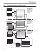
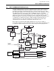
INPUT COMMUNICATION BLOCK
8-20
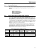
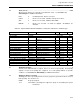
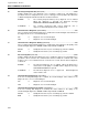
8.3.2 Input Communication Block Parameters
The mnemonics, valid values, and data types for all fields that may be selected for display
and/or be used in making softwiring connections are listed in Table 8-2. The following further
defines the input communication block configuration parameters.
Block Type
IC This is the input communication block type.
Occurrence
1 to 32 There may be up to 32 ‘instances’ allowed of the IC block type.
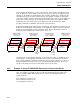
Data Source....................................................................................................................... C – –
The data source information is configured in this block and is used to define the
source of the incoming data.
Instrument Number Instrument Numbers are: 0 to 15. This number represents the
ICN address of the instrument sending the data.
Port Number Port Numbers are: 1 to 3. This number represents which ICN
block should receive the data.
Occurrence Number Occurrence Numbers are: 1 to 16 for MOD 30 XL and Recorder
or 1 to 32 for MOD 30 SLU and MODCELL instruments. This
number represents the output communication point in the
instrument sending the data.
Receive Quality? NO - Data quality is not sent and not expected from MOD 30
instruments
YES - Data quality is sent and is with the data expected from
MODCELL instruments.
Data Type Format of the data to be received may be: CONTINUOUS,
DISCRETE, SHORT STATE, DATE, TIME, CTRL MODE,
LONG STATE, FLOAT PT, ASCII, or MSEC TIME, HEX,
COUNT.
Range Range applies to continuous data only. Enter range in floating
point. The range is applied to the continuous data before it is
stored.
Bottom Indicates the 0% value(low). Default is 0.00000.
Top Indicates the 100% value (high). Default is
100.00000
Maximum Field Size Indicates the maximum number of bytes or characters the data
field can take. Valid values are 1 to 126. This parameter
applies only when receiving hex bytes or ASCII characters.