
User Manual


Logic Functions - Book 2
CONFIGURING THE SEQUENCE BLOCK
11-9
Defining the I/O Modules
The I/O modules required for this application example are as follows:
• Three digital input modules to accept the signals from the high level switch, low level
switch, and the feedback signal from the drain valve.
• One RTD module to accept the product temperature signal (an RTD input function block
is required to condition the signal from the RTD module).
• Two digital output modules to generate the open and close signals for the fill valve and
drain valve.
See
IB-23G600 for more information about I/O modules. Define the I/O modules using the
step-by-step instructions in Table 11-7.
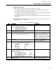
Table 11-7. I/O Module Definition Procedure
1 From the Algorithm window, select the following icons
and place them in the workspace:
3 DIM (Digital Input Modules)
1 WRIM (3-Wire RTD Module)
2 DOM (Digital Output Modules)
2 Double click to query the first DIM. The Digital Input
Module Block properties appear.
3 Select the Name field and type the name LSL-1M. Also
enter the proper slot number for the module.
The default values for all other block
attributes are acceptable without
change. Note that it is not necessary
to specify a number in the Slots field.
The slot location can also be defined
using the I/O Graphic display.
4 Select OK. Note that the assigned tag name now
appears in the DIM block.
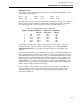
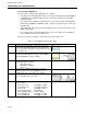
5 Using the procedure of Steps 2 through 4, assign
names to each remaining I/O module as follows:
Second DIM: LSH-1M
Third DIM DrainingM
WRIM TE
First DOM Fill
Second DOM Drain
6 From the Algorithm window, select the following icons
and place them in the workspace. Assign names to
each block as follows
First DI (Digital Input Block) LSL-1
Second DI (Digital Input Block) LSH-1
Third DI (Digital Input Block) Draining
1 RTI (RTD Input Block) TI
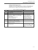
9 Select the RTI block Temperature Scale Field and
select Fahrenheit.
Default entries for all other attributes
are acceptable without change.
10 Select enter to return to the workspace display.