Logic Functions Data Base Reference BOOK 2: Algorithms, Tables and Sequential Logic Functions for 2001P - MODCELL™ Logic Control Identity Module (Version 6) 2004P - MODCELL™ Advanced Control Identity Module (Version 3) 1800P - MOD 30ML™ Identity Module (Version 2)
MicroMod Automation, Inc. The Company MicroMod Automation is dedicated to improving customer efficiency by providing the most cost-effective, application-specific process solutions available. We are a highly responsive, application-focused company with years of expertise in control systems design and implementation. We are committed to teamwork, high quality manufacturing, advanced technology and unrivaled service and support.
PREFACE - BOOK 2 This document is the second of two books that includes database reference information to aid in configuring an instrument with logic functionality. Information on database organization, database memory block structures, I/O functions and communications is described in IB-23G600 Database Reference for Logic Functions - Book 1.
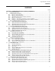
Logic Functions - Book 2 CONTENTS CONTENTS Page SECTION 8 - ALGORITHM FUNCTIONS DATABASE PARAMETERS 8.1 ALGORITHM BLOCKS ...................................................................................................................... 8-1 8.2 EXPRESSION BLOCK (EX) ................................................................................................................. 3 8.2.1 Expression Block Operation.............................................................................................
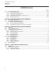
Logic Functions - Book 2 CONTENTS CONTENTS (Cont’d) 8.10 Page TOTALIZER BLOCK (TOT) .................................................................................................................89 8.10.1 Analog Input Examples.................................................................................................................91 8.10.2 Totalizer Block Timing Diagrams..................................................................................................92 8.10.
Logic Functions - Book 2 CONTENTS ILLUSTRATIONS Figure Page 8-1. Functional Block Diagram, Expression Block .............................................................................................. 3 8-2. Expression (EX), General Menu.................................................................................................................. 4 8-3. Expression (EX), Expression Editing Display .............................................................................................. 4 8-4.
Logic Functions - Book 2 CONTENTS ILLUSTRATIONS Figure Page 8-52. Totalizer Block Timing Diagram, DIRECTION = UP, AUTO WRAP = NO ...............................................92 8-53. Totalizer Block Timing Diagram, DIRECTION = UP, AUTO WRAP = YES .............................................94 8-54. Totalizer Block Timing Diagram, DIRECTION = DOWN, AUTO WRAP = NO ........................................95 8-55. Totalizer Block Timing Diagram, DIRECTION = DOWN, AUTO WRAP = YES.............................
Logic Functions - Book 2 ALGORITHM BLOCK SECTION 8 ALGORITHM FUNCTIONS DATABASE PARAMETERS 8.1 ALGORITHM BLOCKS Function blocks (algorithm blocks that execute the logic) cannot operate independently in the instrument database. Groups of related function blocks must be organized into loops. Algorithm blocks are placed in a loop compound. The algorithm block types are: EX Expression Block. Reference IB-23G602 Section 8.2. This block evaluates a user specified expression each time it executes.
Logic Functions - Book 2 ALGORITHM BLOCK SM Supervisory Message Block. Reference IB-23G602 Section 8.9. This block reads, writes, sets, tunes or configures an attribute over the ICN or internally. When SET is selected, all message destination fields are disabled except for the Attribute field. To make a connection with SET enabled, start from the target block and connect to this blocks SETENTRY (signal flow is actually from this block to the selected attribute).
Logic Functions - Book 2 EXPRESSION BLOCK 8.2 EXPRESSION BLOCK (EX) The expression block evaluates a user-specified expression each time it executes. Logical, arithmetic, and conditional operators can be mixed at will in the expression, with the final result being scaled to a configured data type. An auxiliary output can provide the result scaled to another data type.
Logic Functions - Book 2 EXPRESSION BLOCK Figure 8-2. Expression (EX), General Menu Figure 8-3.
Logic Functions - Book 2 EXPRESSION BLOCK Figure 8-4. Expression (EX), Inputs Definition Display Figure 8-5.
Logic Functions - Book 2 EXPRESSION BLOCK 8.2.1 Expression Block Operation Operator precedence in an expression starts with the unary (single operand) operators and continues with the binary (double operand) operators. The order of evaluation can be changed using parentheses or the conditional operators. The order of precedence is: 1. 2. 3.
Logic Functions - Book 2 EXPRESSION BLOCK The INTEGER operator removes the decimal portion of a number, leaving only the integer portion. It does not round the number. For example, INT(12.678) = 12 and INT(_746.21) = _746. The Conditional Operators The conditional operators (IF, THEN, and ELSE) let you specify when operations are evaluated. The IF expression (between the IF and THEN conditionals) is evaluated first. This expression may be enclosed in parentheses.
Logic Functions - Book 2 EXPRESSION BLOCK 8.2.2 Expression Block Parameters The mnemonics, valid values, and data types for all fields that may be selected for display and/or be used in making softwiring connections are listed in Table 8-1. The following further defines the expression block configuration parameters. Block Type EX This is the expression block type. The expression block type code is 15.
Logic Functions - Book 2 EXPRESSION BLOCK Table 8-1.
Logic Functions - Book 2 EXPRESSION BLOCK 00 Block Version (VERSION)................................................................................................. – – R The expression block is at version 3. The functional changes are: 1 Initial Release 2 Added operators for **, ABS, EXP, NLOG, LOG, INT, and the conditional operators IF, THEN, and ELSE. 3 Added Inputs 21 through 46. 02 State (STATE) .......................................................................................................
Logic Functions - Book 2 EXPRESSION BLOCK 07 08 09 10 11 Calc. Error Unacked Quality (CERRUQ) ......................................................................... – WR If the calculation error diagnostic is enabled, this status indicates if the quality of the unacknowledged diagnostic is GOOD or BAD. Only writeable in DEBUG. GOOD 0 Quality when the loop block is RUN or HOLD. BAD 1 Quality when the loop block is OFF. Calc. Error Active (CERRA) ................................................
Logic Functions - Book 2 EXPRESSION BLOCK LOG OF NON POS NUM 6 Same as NLog of non-positive number. ZERO RAISED TO NON POS 7 Attempt to calculate zero to a non-positive power. NUM NEG RAISED TO NON Calculation was completed using 0 for the intermediate result. 8 INTEGER Attempt to calculate a negative number to a non-integer power. Calculation was completed using 0 for the intermediate result.
Logic Functions - Book 2 EXPRESSION BLOCK 48 Result Initial Value (R).......................................................................................................CWR This is the block result after the expression is evaluated. During startup, this is the result initial data value. The initial data value must match the result data type. If NONE is selected, a zero is placed in the result. The result can be enabled (box checked) or disabled (box not checked) by configuration.
Logic Functions - Book 2 EXPRESSION BLOCK 8.2.3 Typical Block Connections for Expression Block Typical softwiring block structures used on softwiring diagrams are shown in Figure 8-6. VCI1 Selector Example Notes This example selects between three inputs by using another expression block that produces a select value. If none of the three are selected, then the previous input (input 4) is selected.
Logic Functions - Book 2 EXPRESSION BLOCK 8.2.4 Expression Block Events The event codes (and their suggested text messages) for the expression block are given below. See the referenced database attributes (in brackets) for additional information. See System Event Block, Logic Functions - Book 1, IB-23G600 for a description of event transitions. 0 1 2 3 4 8.2.
Logic Functions - Book 2 EXPRESSION BLOCK In this example, all variables are on the same scan rate. If the variables have different scan rates, the historian loop can include some expression blocks to average or sample the faster variables so all variables are trended at the same resolution and time base. Alternately, the entire historian can be run at the fastest frequency.
Logic Functions - Book 2 INPUT COMMUNICATION BLOCK 8.3 INPUT COMMUNICATION BLOCK (IC) The input communication block is used to receive data from the output communication block, or output communication block channel for MOD 30 controllers and recorders, or another instrument on the ICN via communication messages. The block specifies the source, data type, and whether quality is to be received with the data.
Logic Functions - Book 2 INPUT COMMUNICATION BLOCK Figure 8-8. Input Communication Block (IC), General Menu Figure 8-9.
Logic Functions - Book 2 INPUT COMMUNICATION BLOCK Figure 8-10. Input Communication Block (IC), Diagnostics Menu 8.3.1 Input Communication Block Operation The Input Communication block is a loop function block that checks the ICN receive buffer to determine if new information has been received, and also whether any source or time-out diagnostic errors have been detected. If no new data has been received for 2 seconds, then the timeout diagnostic is detected.
Logic Functions - Book 2 INPUT COMMUNICATION BLOCK 8.3.2 Input Communication Block Parameters The mnemonics, valid values, and data types for all fields that may be selected for display and/or be used in making softwiring connections are listed in Table 8-2. The following further defines the input communication block configuration parameters. Block Type IC This is the input communication block type. Occurrence 1 to 32 There may be up to 32 ‘instances’ allowed of the IC block type. Data Source ............
Logic Functions - Book 2 INPUT COMMUNICATION BLOCK 02 State (STATE).....................................................................................................................CWR All block state changes are reported as informational events. See Section 2.4.1, State Changes for additional information. RUN 0 Normal Operation. Block is executed. HOLD 1 Block is not executed. Qualities retain previous values. OFF 2 Block is not executed. Qualities will be BAD.
Logic Functions - Book 2 INPUT COMMUNICATION BLOCK 05 06 07 08 09 10 8-22 Receiving unexpected data (SRCSUPP)......................................................................... CWR Indicates whether the source diagnostic error is enabled or suppressed. This diagnostic is provided to detect a configuration error (source or data type incorrect) within either this block or within an Output Communication block in another instrument.
Logic Functions - Book 2 INPUT COMMUNICATION BLOCK 11 12 Timeout Diagnostic Active (TOACT)............................................................................... – WR If the not receiving data diagnostic is enabled, the active status indicates if the diagnostic error is active even after acknowledgement. CLEAR 0 Diagnostic error is not active. ACTIVE 1 Diagnostic error is active. Timeout Diagnostic Active Quality (TOACTQ)...............................................................
Logic Functions - Book 2 INPUT COMMUNICATION BLOCK 8.3.3 Typical Block Connections for Input Communication Block Typical softwiring block structures used on softwiring diagrams are shown in Figure 8-11. For input communications, data quality may or may not be received (see result quality attribute). Continuous Data Data Source (ICN1, Instrument 2, OC3) IC1 Result Result Quality Mode R RQ MODE Softwiring connection to another block with quality logically attached.
Logic Functions - Book 2 OUTPUT COMMUNICATION BLOCK 8.4 OUTPUT COMMUNICATION BLOCK (OC) The output communication block is used to transmit data to an input communication block, or input communication block channel for MOD 30 controllers and recorders, of other instruments on the ICN via communication messages. The block specifies the data destination, data type, and whether quality is to be sent with the data.
Logic Functions - Book 2 OUTPUT COMMUNICATION BLOCK Figure 8-13. Output Communication Block (OC), General Menu Figure 8-14.
Logic Functions - Book 2 OUTPUT COMMUNICATION BLOCK 8.4.1 Output Communication Block Operation The Output Communication block is a loop function block that writes the ICN send buffer every time the instrument gains access to transmit (approximately every 250 milliseconds). When the mode is in auto, the input and its quality are fetched, and placed in the result and result quality fields respectively.
Logic Functions - Book 2 OUTPUT COMMUNICATION BLOCK Occurrence Number Occurrence Numbers are: 1 to 16 for MOD 30 XL and Recorder or 1 to 32 for MOD 30 SLU. This number represents the output communication point in the instrument receiving the data. Data Type Format of the data to be sent may be: COUNT, CONTINUOUS, DISCRETE, STATE, DATE, TIME, CMODE, LSTATE, FLOAT, ASCII, HEX, or MSEC TIME. The data fields (Input, Result, and Data Type) must all be compatible. Range .......................................
Logic Functions - Book 2 OUTPUT COMMUNICATION BLOCK 05 Initial Data Result (R) .........................................................................................................CWR This is the block output value after ranging and mode are applied. During startup, this is the initial data value. The data must match the initial data type. 06 Result Quality (RQ) ............................................................................................................
Logic Functions - Book 2 OUTPUT COMMUNICATION BLOCK 8-30
Logic Functions - Book 2 LINEARIZATION BLOCK 8.5 LINEARIZATION BLOCK (LN) The linearization block produces a linearized value of a floating-point input signal from a specified source, or from a local data value. Several methods of linearization are supported by this block. The method used for a given occurrence of this block is specified by the Linearization Type. Certain attributes of the linearizer block are only present for a given type of linearization.
Logic Functions - Book 2 LINEARIZATION BLOCK Figure 8-17. Linearization (LN), General Menu 8.5.1 Linearization Block Capabilities The Linearization Block has the following linearization capabilities: • Linear • Square and Modified Square • Square Root and Modified Square Root • Piecewise • Inverse Piecewise • Thermocouple (Types B, E, J, K, N, R, S, T) • Inverse Thermocouple (Types B’, E’, J’, K’, N’, R’, S’, T’) • RTD Types (Platinum 0.00385, 0.0003923, 0.003902, 0.003911, and Nickel 0.
Logic Functions - Book 2 LINEARIZATION BLOCK Square and Modified Square Square and modified square linearizations are used when an input signal is proportional to the square root of the measured value. The modified square curve is shown in Figure 8-18. The algorithm is performed on a normalized value (0.0-1.0).
Logic Functions - Book 2 LINEARIZATION BLOCK Modified Square Linearization Curve 210 180 160 140 120 100 80 60 40 20 0 0 20 40 60 80 100 120 140 160 Detailed View (Near Zero) 3 2 1 0 0 2 4 6 8 10 12 14 16 Figure 8-18.
Logic Functions - Book 2 LINEARIZATION BLOCK Modified Square Root Linearization Curve 150 120 100 80 60 40 20 0 0 20 40 60 80 100 120 140 160 180 200 Detailed View (Near Zero) 18 12 8 4 0 0 1 2 3 Figure 8-19.
Logic Functions - Book 2 LINEARIZATION BLOCK Piecewise and Inverse Piecewise When piecewise or inverse piecewise linearization is used, a corresponding piecewise table block must be configured. The piecewise block provides the means to define up to sixty X, Y coordinates for the graph of the linearization function. In performing piecewise linearization, the input value is "fitted" between two points in the table using the X coordinate values (Y values if inverse piecewise is specified).
Logic Functions - Book 2 LINEARIZATION BLOCK 8.5.2 Linearization Block Parameters The mnemonics, valid values and data types for all fields that may be selected for display and/or be used in making softwiring connections are listed in Table 8-4. The following further defines the Linearization Block configuration parameters. Table 8-4.
Logic Functions - Book 2 LINEARIZATION BLOCK Block Type LN This is Linearization Block type. Occurrence 1 to 4096 Distinguishes a particular ‘instance’ of the linearization block. The number is automatically assigned to the block. 02 03 04 05 State (STATE) .................................................................................................................... CWR See Section 2.4.1, State Changes for additional information. RUN 0 Normal Operation. Block is executed.
Logic Functions - Book 2 LINEARIZATION BLOCK 07 08 09 Calc. Error Unacked Quality (CERRUQ) ......................................................................... – WR If the calculation error diagnostic is enabled, this status indicates if the quality of the unacknowledged diagnostic is GOOD or BAD. Only writeable in DEBUG. GOOD 0 Quality when the loop block is RUN or HOLD. BAD 1 Quality when the loop block is OFF. Calc. Error Active (CERRA) .....................................................
Logic Functions - Book 2 LINEARIZATION BLOCK mod sqrt Platinum,0.003850 Platinum,0.003923 Platinum,0.003902 Platinum,0.003911 Nickel,0.006270 23 24 25 26 27 28 Modified Square Root Platinum RTD, Alpha 0.003850 Platinum RTD, Alpha 0.003923 Platinum RTD, Alpha 0.003902 Platinum RTD, Alpha 0.003911 Nickel RTD, Alpha 0.006270 13 Set quality bad on calculation error? (SETQBAD) ......................................................... CWR The result quality can be affected by a calculation error as follows.
Logic Functions - Book 2 LINEARIZATION BLOCK Output Range Desired? ....................................................................................................C – – If the linearization type is linear, square, mod square, square root, or mod sqrt, output ranges may be configured. The ranges must be configured in pairs. If a range pair is not present, the default values are 1.0 for high and 0.0 for low. NO 0 Configured output ranges are not desired. Default values are set.
Logic Functions - Book 2 LINEARIZATION BLOCK 8.5.4 Using the Linearization Block The example in Figure 8-21 shows a typical use of a Linearization Block. The analog input signal is from a differential pressure transmitter measuring flow. The type field of the linearization block is set at MOD SQRT. The block extracts the modified square root of the continuous signal from the transmitter.
Logic Functions - Book 2 PROCESS ALARM BLOCK 8.6 PROCESS ALARM BLOCK (PA) The process alarm block is used to initiate a discrete alarm signal to advise the operator of an irregular process condition. The alarm is calculated by comparing an alarm source with a trip value. The alarm source is usually a value in some other block that the operator wishes to monitor. The type of comparison made is specified by the trip condition.
Logic Functions - Book 2 PROCESS ALARM BLOCK Figure 8-23. Process Alarm Block (PA), General Menu 8.6.1 Process Alarm Block Capabilities Active alarms are determined by comparing the value of the alarm source with the trip value. The order of comparison is: Alarm Input value, Trip Condition, Trip Value. If the result of the comparison is true, the alarm is active. Otherwise, the alarm is clear.
Logic Functions - Book 2 PROCESS ALARM BLOCK HIGH ALARM CALCULATION Alarm Active TRUE FALSE Configured Trip Condition is >= 1000 Alarm Value >= Trip Value Alarm Clear 750 Process Input Floating Point 500 Value Hysteresis Value (50) Alarm Value < Trip Value - Hysteresis 250 0.000000 0 5 10 15 20 Time (Group Scan Cycles) 25 30 35 Figure 8-24. Example of Process Alarm Tripping (Floating Point Data) An alarm can be acknowledged in 1 of 6 ways: • By using the Alarm Acknowledge discrete input.
Logic Functions - Book 2 PROCESS ALARM BLOCK 8.6.2 Process Alarm Block Parameters The mnemonics, valid values, and data types for all fields that may be selected for display and/or be used in making softwiring connections are listed in Table 8-5. The following further defines the Process Alarm block configuration parameters. Block Type PA This is Process Alarm Block type. Occurrence 1 to 4096 Distinguishes a particular ‘instance’ of the process alarm block. The number is automatically assigned.
Logic Functions - Book 2 PROCESS ALARM BLOCK 02 03 State (STATE).....................................................................................................................CWR All block state changes are reported as events. See Section 2.4.1, State Changes for additional information. RUN 0 Normal Operation. Block is executed. HOLD 1 Block is not executed. Qualities retain previous values. OFF 2 Block is not executed. Qualities will be BAD. DEBUG 3 Block is not executed.
Logic Functions - Book 2 PROCESS ALARM BLOCK NOT EQUAL 06 07 08 09 8-48 5 . Alarm becomes active when the Alarm Input is NOT EQUAL to (!=) the Trip Value and becomes clear when the Alarm Input is to EQUAL (==) the Trip Value. Suppress alarm calculation? (SUPPRESS) ....................................................................
Logic Functions - Book 2 PROCESS ALARM BLOCK 10 11 Active Quality (AQ) ........................................................................................................... – WR Writing this output is allowed, but only if the block or its loop is in DEBUG (write will not be reported as an event). GOOD 0 Quality is left GOOD when the quality of the acknowledge input is bad. BAD 1 Quality is set BAD when the quality of the alarm input is bad. Report alarm events? (REPORT) ......................
Logic Functions - Book 2 PROCESS ALARM BLOCK 14 15 Acknowledge Input (ACKINP) ..........................................................................................C – R The acknowledge input is edge triggered so that a value of 0 (FALSE) followed by a value of 1 (TRUE) acknowledges the alarm. NONE No alarm acknowledgement input. However, the alarm can still be acknowledged in other ways as described in Section 8.6.1. LSP Discrete variable is used to acknowledge an alarm and reset the input.
Logic Functions - Book 2 PROCESS ALARM BLOCK 8.6.4 Using the Process Alarm Block The examples in Figure 8-26 show some typical uses of a Process Alarm block.
Logic Functions - Book 2 PROCESS ALARM BLOCK 8.6.6 Process Alarm Block Events The event codes (and their suggested text messages) for the process alarm block are given below. See data base attributes for additional information. See System Event Block, LOGIC FUNCTIONS - BOOK 1, IB-23G600 for event transitions.
Logic Functions - Book 2 TIMER BLOCK 8.7 TIMER BLOCK (TM) The Timer Block is used to perform timing functions for the instrument such as delayed start, delayed stop, pulse duration, interval timing, or periodic self reset timing. When enabled, the timer is a free running timer that adds or subtracts the elapsed time between and during executions (Group Scan Interval from the interface block). A timer can be configured as an up or down timer for a maximum duration of 1193 hours, 2 minutes, 47.
Logic Functions - Book 2 TIMER BLOCK Figure 8-28. Timer Block (TM), General Menu 8.7.1 Timer Block Operation When the timer block executes, its time value is incremented/decremented by the amount of time that has passed between start times of the group scan period in which the timer block exists. That is, the start time of the previous scan of the group is subtracted from the start time of the current scan, and the result is added to/subtracted from the time value when the timer block executes.
Logic Functions - Book 2 TIMER BLOCK TIMER DIRECTION: UP with WRAP ON Reset Input OFF False Disable True High Limit Status True False 4 Timer High Limit 3.5 3 Timer Value Operator Reset Command 2 1.5 Timer Initial Value 1 Timer Low Limit Reset Value 0 0 5 10 15 Time 20 25 30 35 Figure 8-29. Timing Diagram, Up Timer with WRAP = TRUE The timer can be reset via the reset input or the reset command. The reset input causes the timer to be reset when a rising edge is detected.
Logic Functions - Book 2 TIMER BLOCK TIMER DIRECTION: DOWN (no wrap) Reset Input ON OFF Disable False True Timer Low True Limit Status False Timer Initial Value 3 Operator Reset Command Reset Value 2 Timer Value 1 Timer Low Limit 0 0 5 10 15 20 25 30 35 Time Figure 8-30. Timing Diagram, Down Timer with WRAP = FALSE 8.7.
Logic Functions - Book 2 TIMER BLOCK Table 8-6.
Logic Functions - Book 2 TIMER BLOCK 04 Auto Wrap (WRAP)............................................................................................................ CWR Auto wrap is used to determine what action to take when the timer reaches a limit. FALSE 0 Time value is not updated when it reaches a limit. Value must be reset.
Logic Functions - Book 2 TIMER BLOCK 12 Low Limit Status Quality (LLSTATQ) .............................................................................. – WR See Bad Inputs Accepted. GOOD 0 Quality when block is RUN or HOLD and inputs are good. BAD 1 Quality when block is OFF or and input is bad. 13 Reset Command (RESCMD) ............................................................................................
Logic Functions - Book 2 TIMER BLOCK 8.7.3 Time Values All millisecond time values are entered as hours, minutes, seconds, and milliseconds. A time of 1 hour, 17 minutes and 23 seconds would be entered as 01:17:23.000. The maximum time value that can be entered is 1193 hours, 2 minutes and 47.295 seconds. Typical Entry of Time Value Time value 01: 17: 23.000 Hours Value can be set between 0 and 1193 hours Minutes Value can be set between 0 and 59 minutes Seconds.
Logic Functions - Book 2 TIMER BLOCK 8.7.5 Using the Timer Block The following examples show some typical uses of a timer block. EXAMPLE 1 Self Resetting Timer (Figure 8-32) Timer starts timing, time out, reset, starts timing, reset, etc. This cyclic operation provides regular pulses for use by other function blocks and to field devices via a digital output module block. The period of the waveform created by this example is the reset input/limit difference value plus one task scan cycle.
Logic Functions - Book 2 TIMER BLOCK EXAMPLE 3 Timing Only When Disable Source is False (Figure 8-34) When disable source is false, timer will time towards its limit from the current time value. If disable source becomes true, timer will stop and hold the elapsed time. Then, when disable source becomes false, the timer will start to time from the held value and continue to time until the limit is reached.
Logic Functions - Book 2 NOTIFICATION/REQUEST MESSAGE BLOCK 8.8 NOTIFICATION/REQUEST MESSAGE BLOCK (NM) The notification/request message block is used to send a single message over the ICN to the operator and possibly request an answer from the operator. The message actually resides in the operator’s display device and shows up as text on the display. The message can be used to alert the operator to certain conditions relating to the state or progress of the process.
Logic Functions - Book 2 NOTIFICATION/REQUEST MESSAGE BLOCK YES Discrete LSP Send Command Send Source NONE Message Trigger Sets True NO Sets False TRUE Suppress Notification? Active NONE FALSE Operator Write of Data (If Data Requested) Sets False. Max Response Time msec-time msec-time LSP TRUE TRUE Discrete LSP Acknowledge Source NONE Timed Out To: Quality FALSE Check Message Trigger Sets True. Op. Write of Req.
Logic Functions - Book 2 NOTIFICATION/REQUEST MESSAGE BLOCK Figure 8-37. Notification/Request Message Block (NM), General Menu Figure 8-38.
Logic Functions - Book 2 NOTIFICATION/REQUEST MESSAGE BLOCK 8.8.1 Notification/Request Message Block Operation The Notification/Request Message block is a loop function block that sends and receives messages based upon being triggered by a “send” source input transition from 0 to 1 or a send command being issued via operator write. On a warm start, the previous state values for the send input and remote acknowledge input are maintained.
Logic Functions - Book 2 NOTIFICATION/REQUEST MESSAGE BLOCK Is requested data required? .............................................................................................C – – This field specifies whether return data is required from the operator. NO Return data is not required. YES Return data is required. Requested Data Type ........................................................................................................
Logic Functions - Book 2 NOTIFICATION/REQUEST MESSAGE BLOCK 06 07 08 09 Unacked Timeout Diagnostic (TOUNACK)......................................................................– WR If the timeout diagnostic error is enabled, the unacknowledged status indicates if the diagnostic error is or is not acknowledged. NO 0 Diagnostic error is acknowledged. YES 1 Diagnostic error is unacknowledged. Unacked Timeout Diag Quality (TOUNACKQ) ................................................................
Logic Functions - Book 2 NOTIFICATION/REQUEST MESSAGE BLOCK 13 14 15 16 17 18 Msg Unacked Quality (UQ) .............................................................................................. – WR If the transmission of messages is enabled, this status indicates if the quality of the message unacknowledged flag is GOOD or BAD. Only writeable in DEBUG. GOOD 0 Quality when this block (or its controlling loop) is RUN or HOLD.
Logic Functions - Book 2 NOTIFICATION/REQUEST MESSAGE BLOCK 19 Send Source (SENDINP)...................................................................................................C – R Discrete logical source pointer to trigger source. Source of signal that triggers the notification/request transaction. Signal is edge triggered. Trigger 20 21 22 23 8-70 NONE No Send Source; message can only be triggered by an operator write to the Send Command.
Logic Functions - Book 2 NOTIFICATION/REQUEST MESSAGE BLOCK 8.8.3 Typical Block Connections for Notification/Request Message Block Typical softwiring block structures used on softwiring diagrams are shown in Figure 8-39. This example shows a block being used for notification only. NM1 SEND ICN Send Input 1 ICN to Operator Terminal 2 Suppress Notification Report Notif. Events Operator write access to suppress notification, report notification events, acknowledge message, and clear active status.
Logic Functions - Book 2 NOTIFICATION/REQUEST MESSAGE BLOCK 8.8.4 Notification/Request Message Block Events The event codes (and their suggested text messages) for the Notification/Request Message block are given below. See the referenced data base attributes (in brackets) for additional information. See System Event Block, Logic Functions - Book 1, IB-23G600 for a description of event transitions. 0 1 2 3 4 5 8.8.
Logic Functions - Book 2 NOTIFICATION/REQUEST MESSAGE BLOCK EXAMPLE 2 Used for Notification/Request of Discrete Data When the block is configured for data request, a send command is received from a suitable source, e.g., EX1, for the request message (which resides in the terminal) to be displayed. On receipt at the terminal the message is terminal acknowledged. The data requested is entered at the terminal and the Enter key is pressed.
Logic Functions - Book 2 NOTIFICATION/REQUEST MESSAGE BLOCK 8-74
Logic Functions - Book 2 SUPERVISORY MESSAGE BLOCK 8.9 SUPERVISORY MESSAGE BLOCK (SM) The supervisory message block is used to send a single, logic or manually initiated, message over the ICN, or internally (within the MODCELL unit) to an addressable attribute.
Logic Functions - Book 2 SUPERVISORY MESSAGE BLOCK True until transaction complete or failure. Suppressed if Active is True Discrete LSP NONE True Active False True Good Send Input Send Command False Message Trigger Bad Inst. Num. Bottom Port Num. Range LSP Inst.
Logic Functions - Book 2 SUPERVISORY MESSAGE BLOCK Figure 8-43. Supervisory Message (SM), General Menu Figure 8-44.
Logic Functions - Book 2 SUPERVISORY MESSAGE BLOCK 8.9.1 Supervisory Message Block Operation The Supervisory Message block is a loop function block that sends or receives messages based upon being triggered via a “send” source input transition from 0 to 1, or the send command being issued via operator write. On a warm start, the previous state value for the send input is maintained.
Logic Functions - Book 2 SUPERVISORY MESSAGE BLOCK Table 8-8.
Logic Functions - Book 2 SUPERVISORY MESSAGE BLOCK Message Type ................................................................................................................... C – – Specifies the type of transaction the block should attempt when it is triggered. Read Message Types: READ Sends a read request, and when the response is received, stores it in the Result field.
Logic Functions - Book 2 SUPERVISORY MESSAGE BLOCK For other instrument types the attribute address is [Block number],[byte offset]. Use SETENTRY input for SET message types to connect internal attribute. Data Conversion Specifies the type of data conversion to be performed prior to sending or after receiving the message. Valid types of conversions are: millisecond time / time, floating Point / continuous, and NONE. Range....................................................................................
Logic Functions - Book 2 SUPERVISORY MESSAGE BLOCK 05 06 07 Message failure error (FSUPP) ........................................................................................ CWR Indicates whether failure diagnostic error is suppressed. ENABLE 0 Failure diagnostic error is enabled. When this diagnostic is detected, the diagnostic message SUPERVISORY MESSAGE ERROR is reported. SUPPRESS 1 Failure diagnostic error is suppressed. Unacked Failure diag (FUNACK).......................................
Logic Functions - Book 2 SUPERVISORY MESSAGE BLOCK 13 14 15 Fail (FAIL) .......................................................................................................................... – WR Specifies whether the transaction has failed to complete successfully. NO 0 Transaction did not fail and completed successfully. YES 1 Transaction failed. Fail Quality (FAILQ) ..........................................................................................................
Logic Functions - Book 2 SUPERVISORY MESSAGE BLOCK 18 8-84 Locked state 12 Message cannot be accepted because the destination instrument or LOOP is in the locked state. Invalid parameter 14 Message is not accepted because the data value is out of range for the destination attribute. Or, the number of bytes sent as data is unacceptable. Attribute not writeable 15 Message not accepted because that attribute is never writeable.
Logic Functions - Book 2 SUPERVISORY MESSAGE BLOCK 19 20 Result Quality (RQ)......................................................................................................... – WR Indicates the relative quality of the result data. GOOD 0 If message type is READ, result quality is good if the transaction is successful. If message type is READ_W_QUAL, result quality is good if the response quality is good. BAD 1 If message type is READ, result quality is bad if the transaction failed.
Logic Functions - Book 2 SUPERVISORY MESSAGE BLOCK 8.9.3 Typical Block Connections for Supervisory Message Block Typical softwiring block structures are shown in Figure 8-45. This example shows typical connections for read message types. SM1 Send Command SEND ICN 1 ICN to Message Destination 2 Max Response Time Max Number of Retries Operator write access to manually trigger send command, set the max response time and maximum number of times to retry the transaction before failure.
Logic Functions - Book 2 SUPERVISORY MESSAGE BLOCK 8.9.5 Using the Supervisory Message Block The following examples show some typical uses of a supervisory message block. EXAMPLE 1 LSP Triggered Write Message The following example shows a write message transaction. The transaction is triggered by the result of an expression block (EX1) changing from 0 to 1. When the transaction is triggered, the supervisory message block pulls in the current data from the result of the second expression block (EX2).
Logic Functions - Book 2 SUPERVISORY MESSAGE BLOCK EXAMPLE 2 Operator Triggered Read Message The following example shows a read message transaction. The transaction is triggered by an operator write to the send command. When the transaction is triggered, the supervisory message block sends a read request message to the message destination. The message response is stored in the result field.
Logic Functions - Book 2 Totalizer Block 8.10 TOTALIZER BLOCK (TOT) The totalizer block can count an analog input signal by converting the linear analog variable into a number of discrete pulses that are accumulated as a total count. The totalizer has a range of 0.0 to 9999999.0. An input threshold value may be configured to avoid the totalization of extraneous low-level signals. The totalizer function can have an UP or DOWN direction.
Logic Functions - Book 2 Totalizer Block Figure 8-49. Totalizer Block (TOT), General Menu Figure 8-50.
Logic Functions - Book 2 Totalizer Block Figure 8-51. Totalizer Block (TOT), Initialization / Restart Menu 8.10.1 Analog Input Examples The process input is a 4 to 20 ma signal that represents a flow measurement range of 0 to 200 gallons per second. Therefore, the VCI block output range is configured to 0 and 200. The totalizer input is the VCI block result. DIRECTION = UP RATE = SECOND SCALE FACTOR = 1.
Logic Functions - Book 2 Totalizer Block 8.10.2 Totalizer Block Timing Diagrams Totalizer Block Timing Diagram, Figure 8-52, DIRECTION = UP, AUTO WRAP = NO The totalizer will count up until it reaches the high limit. The high limit status will be set TRUE. The count will remain at the high limit until a reset occurs at which time the count will be reset to the low limit. The high limit status will be set to FALSE.
Logic Functions - Book 2 Totalizer Block TRANSITION INPUTS: The transition inputs are evaluated in this order each time the block executes HOLD, RUN, STOP and RESET. For example if a RUN, STOP and RESET transition is detected on the same block execution cycle the total count will be reset to the reset value and the totalizer be in the run condition, but no new counts will be added on any cycle where a reset is detected.
Logic Functions - Book 2 Totalizer Block Totalizer Block Timing Diagram, Figure 8-53, DIRECTION = UP, AUTO WRAP = YES The totalizer will count up until the count value is equal to or greater than the high limit. The high limit status will be set TRUE. When the count is enough to exceed the high limit it will wrap to the low limit value plus any carry over greater than the high limit. The high limit status will remain TRUE while the count is at the high limit.
Logic Functions - Book 2 Totalizer Block Totalizer Block Timing Diagram, Figure 8-54, DIRECTION = DOWN, AUTO WRAP = NO The totalizer will count down until it reaches the low limit. The low limit status will be set TRUE. The count will remain at the low limit until a reset occurs at which time the count will be reset to the high limit. The low limit status will be set to FALSE.
Logic Functions - Book 2 Totalizer Block Totalizer Block Timing Diagram, Figure 8-55, DIRECTION = DOWN, AUTO WRAP = YES The totalizer will count down until the count value is equal to or less than the low limit. The low limit status will be set TRUE. When the count is enough to exceed the low limit it will wrap to the high limit value minus any carry over less than the low limit. The low limit status will remain TRUE while the count is at the low limit.
Logic Functions - Book 2 Totalizer Block 8.10.3 Totalizer Block Parameters The mnemonics, valid values, and data types for all fields that may be selected for display and/or be used in making softwiring connections are listed in Table 8-9. A description of each attribute is provided in the attribute list that follows the table. Initial values are written when the block is initially downloaded. They may be overwritten when the block executes. Table 8-9.
Logic Functions - Book 2 Totalizer Block Table 8-9. Totalizer Block Attributes, Valid Values, Mnemonics, and Data Types (Cont’d) Predetermined Count 1 Status Quality Pred. Count 2 Status Predetermined Count 2 Status Quality Mode Mode Quality Analog Input PC1STATQ GOOD (0), BAD (1) PC2STAT -WR Discrete 22 FALSE (0), TRUE (1) Default value is FALSE. CWR Discrete 23 PC2STATQ GOOD (0), BAD (1) -WR Discrete 24 MODE MODEQ ANALINP RUN (0) or HOLD (1) GOOD (0), BAD (1) The default local value is 0.0.
Logic Functions - Book 2 Totalizer Block 03 04 05 06 07 Bad Inputs (BADINP) .........................................................................................................CWR See Section 2.3.2, Data Quality for additional information. REJECTED 0 Block checks data quality on analog input or pulse input, direction, reset, stop, run and hold inputs are examined on every execution of the block.
Logic Functions - Book 2 Totalizer Block 08 09 Command (CMD) .................................................................................................................-WR The totalizer message commands of RESET and STOP will reset the totalizer when it is received if the direction input quality is GOOD or Bad Inputs are Accepted, regardless of the loop or block state. This attribute provides a dummy location in the database to which commands can be addressed.
Logic Functions - Book 2 Totalizer Block 16 17 18 19 20 21 Total Count Quality (TCQ) ................................................................................................. -WR Quality of Total Count. GOOD 0 Quality when this block or its controlling loop is RUN or HOLD and input quality is GOOD if examined (Bad Inputs Rejected). BAD 1 Quality when this block or its controlling loop is OFF or input quality is BAD if examined (Bad Inputs Rejected). High Limit Status (HLSTAT)...........
Logic Functions - Book 2 Totalizer Block 22 23 24 25 26 Predetermined Count 1 Status Quality (PC1STATQ).......................................................-WR Quality of predetermined count 1 status. GOOD 0 Quality when this block or its controlling loop is RUN or HOLD and input quality is GOOD if examined (Bad Inputs Rejected). BAD 1 Quality when this block or its controlling loop is OFF or input quality is BAD if examined (Bad Inputs Rejected). Predetermined Count 2 Status (PC2STAT)........
Logic Functions - Book 2 Totalizer Block 30 Stop Input (STOPINP)........................................................................................................CWR A FALSE to TRUE transition will reset the total count to the low limit if direction is UP or to the high limit if direction is DOWN and mode will be set to HOLD. Specify a discrete input, or NONE. The initial local value default is FALSE. A remote discrete input is specified by making a connection to the block.
Logic Functions - Book 2 Totalizer Block 8-104
Logic Functions - Book 2 TABLE LIBRARY BLOCKS SECTION 9 TABLE FUNCTIONS DATA BASE PARAMETERS 9.1 TABLE LIBRARY BLOCKS Table function blocks cannot operate independently in the instrument database. These blocks must be placed in a loop compound. Table blocks are selected from the Table library. The piecewise table is the only resource available in this library group. PW Piecewise Table Block.
Logic Functions - Book 2 TABLE LIBRARY BLOCKS
Logic Functions - Book 2 PIECEWISE TABLE BLOCK 9.2 PIECEWISE TABLE BLOCK (PW) The piecewise table block is a data only block. The table consists of two to 60 pairs of X, Y floating point coordinates. Piecewise table can be constructed for supporting a linearization block or as a source of floating point recipe data. In addition, the X and Y coordinates are tuneable parameters.
Logic Functions - Book 2 PIECEWISE TABLE BLOCK Figure 9-2.
Logic Functions - Book 2 PIECEWISE TABLE BLOCK 9.2.1 Piecewise Table Block Operation When a piecewise linearization is specified, the input value to the linearization block is compared to the X coordinate values of the points in the table. The comparison starts with the second point and continues sequentially until either the last point is reached or a point is found for which the X coordinate value is greater than or equal to the input value.
Logic Functions - Book 2 PIECEWISE TABLE BLOCK Piecewise Linearization PIECEWISE TABLE VALUES 100 80 Output of 60 Linearizer Channel (Y Values) 40 20 0 3.5 25.15 46.8 68.45 90.1 Input to Linearizer Channel (X Values) X Values Y Values 3.5 12.0 15.8 21.2 25.5 29.6 33.4 37.3 40.4 43.1 45.4 48.3 52.2 56.1 59.5 63.7 68.6 90.1 0.3 1.5 2.0 3.0 4.5 4.8 7.0 8.3 9.6 10.3 11.8 14.3 17.6 21.0 25.2 31.2 39.4 78.
Logic Functions - Book 2 PIECEWISE TABLE BLOCK 9.2.2 Piecewise Table Block Parameters The mnemonics, valid values, and data types for all fields that may be selected for display and/or be used in making softwiring connections are listed in Table 9-1. The following further defines the piecewise table block configuration parameters. Block Type PW This is the piecewise table block type. The block type code is 13. Occurrence 1 to 4096 There may be up to 4096 ‘instances’ allowed of the PW block type.
Logic Functions - Book 2 PIECEWISE TABLE BLOCK 05 Can Be Inverse Piecewise (CANBEIPW) .........................................................................C – R If the Y values are in ascending order and there are no duplicates, the table is marked as usable for inverse piecewise linearization. 06 Number of Points (NUMPTS) ...........................................................................................C – R The number of point pairs configured. 101, 201 ... 160, 260 X1, Y1 .............
Logic Functions - Book 2 SEQUENCE BLOCK SECTION 10 SEQUENCE BLOCK DATABASE PARAMETERS 10.1 GENERAL This section includes database reference information for the Sequence Block. For information on environmental, communications, and I/O block parameters, see IB-23G600. This reference information includes, block capabilities, a description of block operation, and attribute descriptions. The information is intended to aid the user in understanding and configuring the instrument database.
Logic Functions - Book 2 SEQUENCE BLOCK The Sequence Block allows up to: • 128 inputs • 64 outputs • 512 steps Sequence blocks can be linked together to increase input/output capacity using an External Step Source attribute which is configurable in each block. 10.3 SEQUENCE BLOCK OPERATION A functional block diagram, Figure 10-1, shows basic input/output structures and signal logic flow for the block (signal flow is left to right top to bottom).
Logic Functions - Book 2 SEQUENCE BLOCK External Step Source Step on Cold Start Step on Warm Start Step Determination Logic Auto Semi Auto Step on Reset Manual Mode Output 1 Time Output Manager Output n Transition Expression Evaluation Input 1 Input n Time Quality Bad Inputs Quality Check State No Input (1 through n) Status Pass Through Quality? Yes Figure 10-1.
Logic Functions - Book 2 SEQUENCE BLOCK 10.3.1 Input Processing The block processes each input based on user configuration as follows: • The input is used in transition expressions. • The input is connected directly to one or more outputs. • The input is used for both the transition expressions and direct connection to outputs.
Logic Functions - Book 2 SEQUENCE BLOCK Start Block Execution Update Time in Current Step Yes Step Number Step Source Value ? Step Number External Step Source ? No Zero (0) Evaluate Transition Expression Yes Transition Expression ? No Step No. Equals Current Step No. ? Yes No Change step, set outputs per configuration of new step, and reset time to zero. Remain in current step. Figure 10-2.
Logic Functions - Book 2 SEQUENCE BLOCK 10.3.4 Output Management Upon entry into a new step, the output management function examines the configured outputs. Each output is set to a configured value or previous (same setting as previous step). The output settings remain unchanged until the sequence enters a new step. The value of an output may be different in each step, but must be the same data type. 10.3.
Logic Functions - Book 2 SEQUENCE BLOCK Figure 10-4. Sequence Block, Additional Attributes Menu Figure 10-4.
Logic Functions - Book 2 SEQUENCE BLOCK 10.4.1 Input Definitions The number of inputs, their data types, and their sources are user configured for each sequence, using the Input Definition Menu, Figure 10-4. Up to 128 inputs can be configured in one sequence block. Inputs are specified using the Add button. A menu appears requesting the user to Specify Input Data. The attributes of each input are configured as follows: Name The name format is alphanumeric, and is limited to eight characters.
Logic Functions - Book 2 SEQUENCE BLOCK 10.4.2 Output Definitions The number of outputs and their definitions are user configured for each sequence using the Output Definition Display, Figure 10-6. Outputs may be configured for different values in each step, but can only assume one data type. Output data types and initial data are configured using the Specify Output Data menu; output values for each step are assigned in the Step Definition menus.
Logic Functions - Book 2 SEQUENCE BLOCK 10.4.3 Step Definitions The number of steps, the required output states for each step, and the transition expressions controlling the step progression are user configured for each sequence using the Step Definition Display, Figure 10-6. Up to 512 steps can be defined for one sequence block. The attributes of each step are configured as follows: Step name Enter a step name in this field. The name format is alphanumeric, and is limited to eight characters.
Logic Functions - Book 2 SEQUENCE BLOCK Figure 10-7. Sequence Block Step Display Figure 10-8.
Logic Functions - Book 2 SEQUENCE BLOCK 10.4.4 Transition Expressions The transition expressions are user written equations that can control progression through the steps in a sequence. The block evaluates the transition expressions and either changes to a new step or remains on the current step depending on the result of the evaluation. The result can cause progression to the next sequential step, skipping of steps, and return to previous steps.
Logic Functions - Book 2 SEQUENCE BLOCK 10.4.5 Attribute Descriptions The mnemonics, valid values, and data types for all fields that can be selected for display and/or be used in making softwiring connections are listed in Table 10-1. A description of each attribute is provided in the attribute list that follows the table. The following conventions are used in presenting the attribute information in Table 10-1.
Logic Functions - Book 2 SEQUENCE BLOCK Table 10-1.
Logic Functions - Book 2 SEQUENCE BLOCK Table 10-1.
Logic Functions - Book 2 SEQUENCE BLOCK 00 Version (VERSION) ...............................................................................................................--R The valid version is 1. 01 Block Length (BLKLEN) .......................................................................................................--R 02 Block State (STATE)..........................................................................................................
Logic Functions - Book 2 SEQUENCE BLOCK 07 08 09 10 11 12 13 Input Error Unacked Quality (CERRUQ)......................................................................... – WR If the bad input error diagnostic is enabled, this status indicates if the quality of the unacknowledged diagnostic is GOOD or BAD. Only writeable in DEBUG. GOOD 0 Quality when the block STATE is RUN or HOLD. BAD 1 Quality when the block STATE is OFF. Input Error Active (CERRA) ...........................................
Logic Functions - Book 2 SEQUENCE BLOCK 14 15 16 17 18 19 20 10-18 Calculation Error Active Quality (CERRAQ) ...................................................................– WR If the calculation error diagnostic is enabled, this status indicates if the quality of the active diagnostic is GOOD or BAD. Only writeable in DEBUG. GOOD 0 Quality when the block STATE is RUN or HOLD. BAD 1 Quality when the block STATE is OFF. Bad Step Error (INVSTS) ..............................................
Logic Functions - Book 2 SEQUENCE BLOCK 21 22 23 24 25 Failure Error Unacked (FAILU) ....................................................................................... – WR If the failure error diagnostic is enabled, the unacknowledged status indicates if the diagnostic is or is not acknowledged. Only writeable in DEBUG. NO 0 Diagnostic error is acknowledged. YES 1 Diagnostic error is unacknowledged. Failure Error Unacked Quality (FAILUQ) ....................................................
Logic Functions - Book 2 SEQUENCE BLOCK 27 28 Step on Reset (RSTEP)..................................................................................................... CWR The step to which the sequence is driven when a reset command is written in Attribute 34. PREVIOUS The step prior to the current operating step Count Number of any configured step. Step on Fail (FSTEP).........................................................................................................
Logic Functions - Book 2 SEQUENCE BLOCK 32 33 34 35 Status (STATUS) ................................................................................................................. -WR This is the operating status of the block. RUNNING, WAITING, and FROZEN are writeable only on debug. NOT INITIATED 0 RUNNING 1 Normal operation WAITING 2 Progression through the sequence is suspended. The sequence remains on the current operating step until a run command is received.
Logic Functions - Book 2 SEQUENCE BLOCK 39 Current Step (STEP)............................................................................................................-WR The current operating step in the sequence as determined by the step determination logic. See Section 10.2.1 Sequence Block Operation for more information. Only writeable when Mode is MANUAL or State is DEBUG. 40 Current Step Quality (STEPQ) ...........................................................................................
Logic Functions - Book 2 SEQUENCE BLOCK 44 Pass Through Quality? (QPASS) CWR Allows the quality of inputs which are designated as outputs to be passed through the block to the outputs, thus transferring quality checking responsibility to the receiver of the outputs. NO 0 Input quality is not passed through the block to the outputs. YES 1 Input quality and values are passed through the block to the outputs. 46 Time in Step (TIME) ......................................................................
Logic Functions - Book 2 SEQUENCE BLOCK Syntax Errors: ESTACK OVERFLOW 20 INPUT NOT FOUND MISALIGNED OPERAND UNKNOWN OPERAND TYPE UNKNOWN CONSTANT TYPE MISALIGNED CONSTANT READ FROM EMPTY STACK 21 22 23 24 25 26 UNKNOWN OPERATOR DATA TYPE VIOLATION 27 28 There was not sufficient evaluation stack to complete the calculation. One of the input operands was not found. Input operand token at odd address. Unknown data type found for input operand. Unknown data type found for constant operand.
Logic Functions - Book 2 SEQUENCE BLOCK 501 503 505 through 559 502 504 506 through 560 10.5 Output 1 (OUT 1)................................................................................................................. -WR Output 64 (OUT64).............................................................................................................. -WR Each block output is the data value specified by the output definition as configured for the current operating step in a sequence.
Logic Functions - Book 2 SEQUENCE BLOCK 10-26
Logic Functions - Book 2 CONFIGURING THE SEQUENCE BLOCK SECTION 11 CONFIGURING THE SEQUENCE BLOCK 11.1 GENERAL Configuring a batch application is easier than ever with the Visual Application Designer (ViZapp) Software. Comprehensive ViZapp user information is available in the ViZapp help files (vizapp.hlp) and the ViZapp Tutorial (IB-VIZAPP-TUT). A simple batch process application has been chosen as an example because of the virtually limitless numbers of different configurations possible.
Logic Functions - Book 2 CONFIGURING THE SEQUENCE BLOCK 11.2.1 Sequence Description The operations necessary to cook a batch of product require six basic steps. The steps and the actions determining the progression from one step to the next are shown in the flow chart, Figure 11-2.
Logic Functions - Book 2 CONFIGURING THE SEQUENCE BLOCK 11.2.2 Configuration Procedure Getting Started This procedure is based on the assumption that the ViZapp software is installed. Start the configuration of the Sequence Block using the step-by-step instructions in Table 11-1. Table 11-1. Starting the Configuration Step 1 2 3 4 5 6 7 8 9 Procedure Launch ViZapp. Use the desktop icon or select Programs from the Windows Start menu and select ViZapp from the menu.
Logic Functions - Book 2 CONFIGURING THE SEQUENCE BLOCK Placing the Loop Compound and Sequence Block A Loop Compound ( Loop Cpd) must be placed in the workspace to contain the function blocks. The compound has a single Loop Block, and the functions within the loop block are part of the scan group for the loop. Place the Loop Compound symbol and sequence block using the instructions in Table 11-2. Table 11-2.
Logic Functions - Book 2 CONFIGURING THE SEQUENCE BLOCK Defining the Inputs An important feature of the Sequence Block is its ability to accept input names and use the names in the step logic. This makes it easy to examine a previously configured block and understand the logic. Input names are limited to eight characters and are not case sensitive. The inputs to this sequence and their assigned names (in brackets) are as follows: • The start signal from the operator pushbutton.
Logic Functions - Book 2 CONFIGURING THE SEQUENCE BLOCK Defining the Outputs The number of outputs and their definitions are user configured for each sequence using the Outputs menu. Outputs may be configured for different values in each step, but can only assume one data type. Output data types and initial data are configured using the Specify Output Data menu; output values for each step are assigned in the Step Definition menus. One output may be assigned multiple values for different steps.
Logic Functions - Book 2 CONFIGURING THE SEQUENCE BLOCK Defining the Steps The sequence for this application requires six steps as described in Section 11.2.1. These steps can be named as follows: Step 1 Step 2 Idle Fill Step 3 Step 4 Heat Cook Step 5 Step 6 Cool Drain The output state for each of the three outputs must be defined for each step. For example, in the Idle step, the fill valve (Output 1) and drain valve (Output 2) must both be shut (False).
Logic Functions - Book 2 CONFIGURING THE SEQUENCE BLOCK Table 11-6. Step, Output and Transition Logic Definition Procedure Step 1 2 3 Procedure On the SEQ properties display, select the Steps menu. Select Add and type the Step name Idle. Enter the transition expression IF LevelLO && !Draining THEN Fill Comments This is the expression required to control the change from Idle (Step 1) to Fill (Step 2).
Logic Functions - Book 2 CONFIGURING THE SEQUENCE BLOCK Defining the I/O Modules The I/O modules required for this application example are as follows: • Three digital input modules to accept the signals from the high level switch, low level switch, and the feedback signal from the drain valve. • One RTD module to accept the product temperature signal (an RTD input function block is required to condition the signal from the RTD module).
Logic Functions - Book 2 CONFIGURING THE SEQUENCE BLOCK Connecting the I/O Modules The connections required for this application are as follows: • The output from each digital input module is connected to a digital input block (MODOUT to MODIN) and the digital input block must be connected to an input on the StepMgr (Sequence Block).
Logic Functions - Book 2 CONFIGURING THE SEQUENCE BLOCK Compiling and Downloading the Project The final phase of the configuration procedure is to compile the configured database. The compilation function puts the configuration data into a file that can be downloaded to an instrument. Initiate the compilation operation using the instructions in Table 11-9. Table 11-9. Database Compilation Procedure Step 1 2 3 4 Procedure Save the database before compiling or downloading.
Logic Functions - Book 2 CONFIGURING THE SEQUENCE BLOCK 11-12
The Company’s policy is one of continuous product improvement and the right is reserved to modify the information contained herein without notice, or to make engineering refinements that may not be reflected in this bulletin. Micromod Automation assumes no responsibility for errors that may appear in this manual. © 2004 MicroMod Automation, Inc. Printed in USA IB-23G602, Issue 5 3/2005 MicroMod Automation, Inc. 75 Town Center Drive Rochester, NY USA 14623 Tel. 585-321-9200 Fax 585-321-9291 www.