Output Holder for Controllers Product Description, Installation and Wiring for 1750N Output Holder Instructions
MicroMod Automation, Inc. The Company MicroMod Automation is dedicated to improving customer efficiency by providing the most cost-effective, application-specific process solutions available. We are a highly responsive, application-focused company with years of expertise in control systems design and implementation. We are committed to teamwork, high quality manufacturing, advanced technology and unrivaled service and support.
Output Holder Instructions CONTENTS CONTENTS Page SECTION 1 – PRODUCT DESCRIPTION 1.1 1.2 1.3 1.4 1.5 1.6 1.7 OVERVIEW ............................................................................................................................1-1 FEATURES .............................................................................................................................1-1 Related Information ........................................................................................................
Output Holder Instructions CONTENTS 4.7 4.8 4.9 4.10 4.11 4.12 4.13 4.14 4.15 4.16 4.17 4.18 4.19 4.20 4.21 4.16 4.23 4.24 5.1 Opening Component Gallery.................................................................................................. 4-8 Component Gallery................................................................................................................. 4-9 Un-compounding the Compound ...........................................................................................
Output Holder Instructions PRODUCT DESCRIPTION SECTION 1 PRODUCT DESCRIPTION 1.1 OVERVIEW For safe operation some processes require that valve position be maintained above a closed position even when a controller might be removed for service or replacement. The 1750N Output Holder is capable of identifying a controller’s output fault and to maintain the last good value to the field control device for safe operation.
Output Holder Instructions PRODUCT DESCRIPTION 1.3 RELATED INFORMATION A general description of the MODCELL and MOD 30ML instruments, mechanical installation instructions, electrical connection instructions, and communication connection instructions can be found in the following documents.
Output Holder Instructions PRODUCT DESCRIPTION 1.4 EXPLANATION OF CATALOG NUMBERS The products described in this book have catalog numbers that help identify specific features. In addition, some products are assigned a serial number which can be used to track manufacturing data. The catalog number stamped on the product data contains a series of single and multiplecharacter codes. These codes provide specific information concerning various electrical and/or structural options.
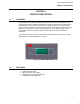
Output Holder Instructions PRODUCT DESCRIPTION 1.6 BASIC HARDWARE The 1750N, Figure 1-1, is designed for mounting in a panel with a 11.5 inch depth. The instrument housing contains a 6-point termination facility which accepts all instrument I/O and power connections. The 4-20mA output from the MOD 30ML controller is wired in series with the 1750N, and then to the field.
Output Holder Instructions PRODUCT DESCRIPTION 1.7 SPECIFICATIONS ANALOG INPUT INPUT/OUTPUT CHARACTERISTICS Span (0 to 100%) 4 to 20 mA Analog input resistance 250 ohms typical Lower Limit 2.72 mA Analog output (I out) Resistance 50 kohms min Upper Limit 21.28 mA Open circuit output voltage 24V dc max ANALOG OUTPUT (I out) ANALOG OUTPUT LOAD CAPABILITY Span (0 to 100%) 4 to 20 mA Resistance 800 ohms max Lower Limit 2.72 mA Capacitance 10 micro F max Upper Limit 21.
Output Holder Instructions PRODUCT DESCRIPTION 1 -6
Output Holder Instructions MECHANICAL INSTALLATION SECTION 2 MECHANICAL INSTALLATION 2.1 OVERVIEW Read these instructions thoroughly before starting installation. Installation personnel should be qualified technicians.. 2.2 Displays and Cleaning The display is protected by an overlay that can be removed after installation. The face of the display, while made of scratch-resistant plastic, can be abraded by harsh materials such as paper towels and industrial wipes.
Output Holder Instructions MECHANICAL INSTALLATION • The panel provides rigid support for a fully loaded 5.5-pound (2.5 kg) controller and any other panel devices. • Electrical wiring routing and support are planned. Mount the output holder as follows: 1. Prepare the panel as indicated in Figure 2-1. 2. Slide instrument into panel cutout. 3. Insert brackets into slots in top and bottom of instrument housing. 4. Tighten retaining screws to a torque of 5 inch-pounds (0.
Output Holder Instructions POWER, GROUNDING, AND I/O CONNECTIONS SECTION 3 POWER, GROUNDING, AND I/O CONNECTIONS 3.1 OVERVIEW Read this section thoroughly before making any connections. Installation personnel should be qualified technicians. Observe all electrical code requirements and safety standards applicable to these wiring procedures. Specific instructions and connection diagrams for the various built-in inputs and outputs are provided in the following sections.
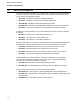
Output Holder Instructions POWER, GROUNDING, AND I/O CONNECTIONS 24 VDC Power + – Controller Output AOUT or 2003A 4-20mA + O.H. Sense Input 2006A Contact Closure to TCI + Output Track Input AIN or 2002A 1-5mA to OPTI – 1750N Output Holder 1 +24 VDC from Power Supply 2 Power Supply and Signal Commons 3 4-20mA Output from Controller 4 1-5mA Monitor to Controller 5 O.H. Sense to Controller (internally tied to Common) 6 4-20mA Output to Field Device – + – Field Device Figure 3 .2.
Output Holder Instructions CONFIGURATION SECTION 4 CONFIGURATION 4.1 OVERVIEW The Compound Gallery in the ViZApp (Visual Application Builder) software includes a compound called PID_OH. This section explains how to configure MOD 30ML or Modcell using this compound for use with the Output Holder. The purpose of this compound is to cause the control loop to synchronize its output holder before turning its field output on. This will in turn cause a bump less transfer.
Output Holder Instructions CONFIGURATION 4. The Component Gallery dialog will be displayed as shown in the next figure. Select the Compounds tab and click on the PID_OH compound from the list of compounds as shown and then click on the Export button. Figure 4 .2. Component Gallery The Compound will be placed in your database. The function blocks are located inside this compound. You can un-compound the loaded PID_OH compound.
Output Holder Instructions CONFIGURATION Figure 4 .3. Un-compounding the compound After you un-compounded the PID_OH compound, it will be displayed as shown in the next figure.
Output Holder Instructions CONFIGURATION Figure 4 .4. PID_OH Compound The compound has the following function blocks: Block Name pid disp TuningList PV Pv_i op_ao RETURN Type PID DISP TL AIN VCI AOUT AIN RETURNF1 VCI SENSE SENSEF OP_T_LGC DIM DI EX Description The PID control block Display for the PID Tuning list for the PID Built-in input used for PV Signal conditioning for the AIN Built-in analog output block Built-in input used to get the feedback from the output holder.
Output Holder Instructions CONFIGURATION 1. The compound uses an AIN (Built-in Analog Input) block configured as current input (420mA) and a VCI block for ranging it to 0-100 engineering units linear. It also has a builtin AOUT block. You can substitute different type of input or module, conditioning and analog output blocks 2. The compound also has preconfigured PID, Display and Tuning List blocks, which you can substitute with your existing blocks in your database. 3.
Output Holder Instructions CONFIGURATION with the RUNINIT signal from the Interface (IF) block is used in the EX block to enable output tracking in the PID block. The logic configured in the EX block OP_T_LGC is as shown below: SENSE && RUNINIT In the above expression && is the logical AND function. The RUNINIT signal from the IF block goes high momentarily upon controller startup. If the output holder is not present, the PID block does not have to switch its output to track mode upon start up.
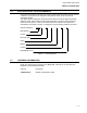
Output Holder Instructions CONFIGURATION Figure 4 .6. Execution Order If you are using the MOD30 Conversion Style Instrument, change Input Signal Range of PV to 1 to 5 Volts and RETURN to 0.25 to 1.25 Volts. 8. Optionally you can include the output holder feedback (RETURN) only in the configuration and not the presence of the output holder (SENSE). In this case you do not need the discrete input module in the controller.
Output Holder Instructions CONFIGURATION 4.3 LOADING THE COMPOUND FOR MODCELL The PID_OH compound has a fully functional PID, with I/O and also the logic for bumpless transfer of output. If you already have your PID configured, you can delete the blocks that are not required from this compound after loading. 1. Launch the ViZapp Software and open your workspace, project and the instrument database. 2. The PID_OH1 compound can only be loaded inside a loop compound.
Output Holder Instructions CONFIGURATION Figure 4 .8. Component Gallery The Compound will be placed in your database. The function blocks are located inside this compound. You can un-compound the loaded PID_OH compound. With the loaded compound selected, select Objects – Uncompound from the menu bar.
Output Holder Instructions CONFIGURATION Figure 4 .9. Un-compounding the compound After you un-compounded the PID_OH compound, it will be displayed as shown in the next figure.
Output Holder Instructions CONFIGURATION Figure 4 .10. PID_OH1 Compound The compound has the following function blocks: Block Name pid PV Pv_i op_ao RETURN Type PID VCIM VCI AOM VCIM RETURNF1 VCI SENSE SENSEF OP_T_LGC DIM DI EX Description The PID control block Voltage/Current Input block used for PV Voltage/Current Signal conditioning for the AIN Analog output block Voltage/Current input used to get the feedback from the output holder. Configured as 1-5 mA Signal conditioning for the AIN.
Output Holder Instructions CONFIGURATION 3. The compound uses a VCIM (RETURN) and a VCI conditioning (RETURNF1) blocks for reading the feedback from the output holder. This is the feedback of the output value from the output holder sent to the field. This value is tied to the output track input (OPTI) of the PID block so that the PID block tracks this value upon start up. This is how a bump less transfer of output value is achieved.
Output Holder Instructions CONFIGURATION it will switch to zero values. To avoid this a momentary faulty value (negative 25) is introduced at the startup and then the PID block’s output will override this value. 5. The compound uses a Digital input block (DIM - SENSE) and a digital conditioning block (DI – SENSEF) to sense the presence of the output holder. This discrete signal along with the RUNINIT signal from the Interface (IF) block is used in the EX block to enable output tracking in the PID block.
Output Holder Instructions CONFIGURATION Figure 4 .12. Execution Order 8. Optionally you can also include the feedback (RETURN) only in the configuration and not the presence of the output holder (SENSE). In this case you do not need the discrete input module in the controller. The configuration will not have the SENSE (DIM), SENSEF (DI) and the OP_T_LGC (EX) blocks. You can delete these blocks from the loaded compound. You would still need to connect a track command input to the PID block.
Output Holder Instructions CONFIGURATION 4.4 CONNECTING RUNINIT FROM THE IF BLOCK Option1: When using both RETURN and SENSE signals from the output holder: To connect the RUNNIT attribute from the IF block, refer to the section select the connector (multi segment or right angle) from the Algorithms Window and then click on a blank area of the instrument document near the EX block. Figure 4 .13. Connection Menu Select Compound External from the menu as shown above. Figure 4 .14.
Output Holder Instructions CONFIGURATION Figure 4 .15. IF block attributes Select the RUNINIT attribute from the list and click on the OK button. Drag the connection line to the EX block and click on it. Figure 4 .16.
Output Holder Instructions CONFIGURATION Figure 4 .17. EX block Connection Input Select the user Input RUNINIT and click on OK. The connection is complete now. See the next figure: Figure 4 .18.
Output Holder Instructions CONFIGURATION Option2: When using only the RETURN signal from the output holder: To connect the RUNNIT attribute from the IF block, refer to the section select the connector (multi segment or right angle) from the Algorithms Window and then click on a blank area of the instrument document near the EX block. Figure 4 .19. Connection Menu Select Compound External from the menu as shown above. Figure 4 .20.
Output Holder Instructions CONFIGURATION Figure 4 .21. IF block attributes Select the RUNINIT attribute from the list and click on the OK button. Drag the connection line to the PID block and click on it. Figure 4 .22.
Output Holder Instructions CONFIGURATION Figure 4 .23. Connection to PID block Select the user Input TCI and click on OK. The connection is complete now. See the next figure: Figure 4 .24.
Output Holder Instructions CONFIGURATION 4.5 THEORY OF OPERATION When the instrument powers up the process value is read first followed by the RETURN and SENSE inputs. The expression block OP_T_LGC is executed next with a result that becomes true when both the SENSE and RUNINIT inputs are true. The SENSE input will always be true when an output holder is present. The RUNINIT input is true only for a moment when the instrument powers up.
Output Holder Instructions OPERATION AND MAINTAINANCE SECTION 5 OPERATION AND MAINTAINANCE 5.1 OVERVIEW This chapter provides operating instruction and maintenance information for the output holder instrument. 5.2 OPERATION The output holder can display the controller’s output in a 10 segment horizontal bar graph. It has 2 keys (UP and DOWN) that enable manual output adjustment in the absence of the main controller. Operator activity available during runtime: 5.2.
Output Holder Instructions OPERATION AND MAINTAINANCE 5.2.2 CONTROL KEYS The operator control keys are: Used to ramp up the output holder’s output when the controller output is not valid. Used to ramp down the output holder’s output when the controller is not valid. 5.2.3 BAR DISPLAY The 10 segment horizontal bar graph provides visual indication of the output holder’s output. Each segment represents up to 10 % of the output.
Output Holder Instructions OPERATION AND MAINTAINANCE 5.3 TROUBLESHOOTING AND MAINTAINANCE Indication Possible Cause Solution The bar graph does not show any indication The output is zero percent. This is because each segment in the bar graph represents 10 % of the value. Each segment has varying light intensity to represent any intermediate value.
Output Holder Instructions OPERATION AND MAINTAINANCE Notes: 5 -4
The Company’s policy is one of continuous product improvement and the right is reserved to modify the information contained herein without notice, or to make engineering refinements that may not be reflected in this bulletin. Micromod Automation assumes no responsibility for errors that may appear in this manual. © 2004 MicroMod Automation, Inc. Printed in USA IB-1750N-INS, Issue 2 12/2004 MicroMod Automation, Inc. 75 Town Centre Drive Rochester, NY USA 14623 Tel. 585-321 9200 Fax 585-321 9291 www.