
Users Guide User Manual


IB-23C003
APPENDIX B - CONNECTOR DESCRIPTIONS
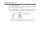
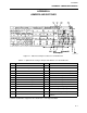
Table B-2. Mini Link RS-232 Connector Pinout
* Pin 9 can be configured to present Mini Link's 5VDC (for test purposes only) by using jumper W22.
I/O Pin Signal Name I/O
1 GND GND
2 RXDATA I
3 TXDATA O
4 NC -
5 GND GND
6 NC -
7 RTS I
8 CTS O
9* NC -
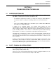
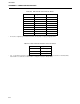
Table B-3. Mini Link ICN0 and ICN1 Connector Pinout
* Two- or Three-Wire Connection for ICN0 and ICN1. The (+) and (-) terminals accept signals from the ICN. The third terminal,
labeled "GND" is used when the Isolation Feature is employed (see jumper setting for W23).
Terminal Signal Name*
1 IBUS(+)
2 IBUS(–)
GND GND
B-2