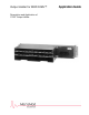
Output Holder for MOD 30ML™ Description and Application of 1726F Output Holder Application Guide
MicroMod Automation, Inc. The Company MicroMod Automation is dedicated to improving customer efficiency by providing the most cost-effective, application-specific process solutions available. We are a highly responsive, application-focused company with years of expertise in control systems design and implementation. We are committed to teamwork, high quality manufacturing, advanced technology and unrivaled service and support.
Using The Output Holder With MOD 30ML Contents CONTENTS INTRODUCTION ...........................................................................................................................................1 SCOPE ..........................................................................................................................................................1 FIRMWARE VERSIONS.........................................................................................................................
Using The Output Holder With MOD 30ML Contents ii
Using The Output Holder With MOD 30ML Introduction INTRODUCTION SCOPE This book is one of a series that discusses the application of MOD 30ML™ to commonly encountered process control loops. This book discusses use of the 1726F Output Holder with the MOD 30ML controller. The primary purpose of this document is to identify the function of the output holder, how to connect an output holder card to the MOD 30ML Controller and how the output holder compound strategy interfaces with the hardware.
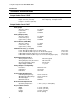
Using The Output Holder With MOD 30ML Introduction TECHNICAL SPECIFICATIONS Output Holder Panel 1725F Width - 19-inches (483-mm) Depth - 6-inches (153-mm) Height - 3-1/2-inches (89-mm) Weight - 4 lbs. 9-1/2 oz. (2.08 kg) max. Panel Capacity - 6 Output Holders Output Holder Card 1726F Analog Input Span (0 to 100%) Lower Limit Upper Limit 4 to 20mA 2.72mA 21.28mA Analog Output (I OUT) Span (0 to 100%) Lower Limit (-8%) Upper Limit (+ 108%) 4 to 20mA 2.72mA 21.
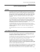
Using The Output Holder With MOD 30ML Output Holder Purpose OUTPUT HOLDER PURPOSE GENERAL For safe operation some processes require that valve position be maintained above a closed position even when a controller might be removed for service or replacement. The Output Holders task is to identify a controller output fault and to maintain the last good value to the field control device for safe operation.
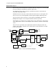
Using The Output Holder With MOD 30ML Output Holder Purpose value is being sent to the field the Clock Control permits the clock pulses to reach the D/A Converter causing it to float with the controllers output value. The Up/Down Counter counts clock pulses and either increments or decrements the count value at its parallel output. The D/A Converter receives the counters value and converts it to a 1-5 Vdc signal. This value is in turn sent to the Analog MUX circuit through the Output Conditioning circuit.
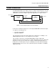
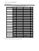
Using The Output Holder With MOD 30ML Output Holder Purpose WIRING & CONNECTIONS Figure 2 provides a generic reference as to the signal paths between the controller and the 1726F Output Holder card. Table 1 provides a complete output holder wire color and signal listing as viewed from the 1751FZ output holder cable. This is required to provide detailed wire connection for multiple output holder applications to a single controller.
Using The Output Holder With MOD 30ML Output Holder Purpose Table 1. Output Holder Cable Wire Definitions Twisted Pair # 1 2 3 4 5 6 7 8 9 10 11 12 13 14 15 16 17 18 Colors wht blu wht org wht grn wht brn wht slate red blu red org red grn red brn red slate blk blu blk org blk grn blk brn blk slate yel blu yel org yel grn P1 Conn. Pin # 1 19 2 20 3 21 4 22 5 23 6 24 7 25 8 26 9 27 10 28 11 29 12 30 13 31 14 32 15 33 16 34 17 35 18 36 Note: 1. Be sure this is common with the controllers DC common.
Using The Output Holder With MOD 30ML MOD 30ML Application MOD 30ML APPLICATION GENERAL Figure 3 shows a block diagram of the output holder compound strategy. This strategy contains the PID, display and I/O for one loop. When using this compound you will be required to complete a few strategy changes to make it fit your application. These changes are outlined in Loading the Compound.
Using The Output Holder With MOD 30ML MOD 30ML Application LOADING THE COMPOUND The following procedure assumes that the Application Builder is open, you are in a Loop Block and the output holder compound is located in the compounds directory of the Application Builder. To load the output holder compound (PID_OPH.CSM): 1. Select the Compounds icon mouse key (see Figure 1). located at the top of the screen using the right from the Compounds menu. A directory menu will appear. If the 2.
Using The Output Holder With MOD 30ML MOD 30ML Application menu will appear with the tag name you gave the output holder compound. Select that tag and hit “OK”. A new menu will appear with the attribute “RUNINIT” in it. Select “RUNINIT”. The connection is now complete. Release the connection tool by clicking the right mouse key. 12. Double click on the oval loop block to return to the compound block. Enter all of the necessary engineering values in the Input Conditioning and PID blocks.
Using The Output Holder With MOD 30ML MOD 30ML Application OUTPUT HOLDER COMPOUND THEORY OF OPERATION When the instrument powers up the process value is read first followed by the Return and Sense inputs. The expression block “OP_T_LGC” is executed next with a result that becomes true when both the sense and run initialization inputs are true. The sense input will always be true when an output holder card is present.
The Company’s policy is one of continuous product improvement and the right is reserved to modify the information contained herein without notice, or to make engineering refinements that may not be reflected in this bulletin. Micromod Automation assumes no responsibility for errors that may appear in this manual. © 2004 MicroMod Automation, Inc. Printed in USA IB-MLAPP-OH, Issue 2 04/2005 MicroMod Automation, Inc. 75 Town Centre Drive Rochester, NY USA 14623 Tel. 585-321 9200 Fax 585-321 9291 www.