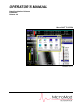
OPERATOR’S MANUAL Data Visualization Software 53PW6000 Release 4.0 Micro-PWC™ SYSTEM PN26004 Rev.
MicroMod Automation, Inc. The Company MicroMod Automation is dedicated to improving customer efficiency by providing the most ost-effective, application-specific process solutions available. We are a highly responsive, application-focused company with years of expertise in control systems design and implementation. We are committed to teamwork, high quality manufacturing, advanced technology and unrivaled service and support.
Micro-PWC OPERATOR’S MANUAL TABLE OF CONTENTS 1.0 - Introduction .......................................................................... 1 1.1 Intended Audience......................................................................................... 1 1.2 Functional Description .................................................................................. 1 1.2.1 User Interface................................................................................... 1 1.2.2 Micro-PWC Management Features...
Micro-PWC OPERATOR’S MANUAL 2.4.7 Show Users and Screen Contents ................................................. 18 2.4.8 Arrange Windows Function ............................................................ 18 2.5 Summary - Window Types, Components, and Operations.......................... 19 3.0 - Micro-PWC Features.......................................................... 21 3.1 Introduction.................................................................................................. 21 3.
Micro-PWC OPERATOR’S MANUAL 4.2.1 Accessing the Summary Display.................................................... 40 4.2.2 Using the Summary Display ........................................................... 41 4.3 The Group Display....................................................................................... 43 4.3.1 Accessing the Group Display ......................................................... 43 4.3.2 Group Display.......................................................................
Micro-PWC OPERATOR’S MANUAL 6.1.11 Info Button .................................................................................... 62 6.1.12 Compression Button and Arrows.................................................. 62 6.1.12.1 Trend Compression Speed Factors ........................... 65 6.1.13 Zoom/Unzoom Button .................................................................. 65 6.1.14 Reset Button................................................................................. 66 6.1.
Micro-PWC OPERATOR’S MANUAL 9.0 - Events ................................................................................. 87 9.1 Introduction.................................................................................................. 87 9.2 System Events in the Mini-Alarm Window ................................................... 87 9.2.1 Audible Alarm Format for Event Messages.................................... 87 9.2.2 Acknowledging Event Messages in the Mini-Alarm Window .......... 87 9.2.
Micro-PWC OPERATOR’S MANUAL 11.1.2 Notes on DAT Tape Drive Use.................................................... 106 11.2 Backup and Restore ................................................................................ 107 11.2.1 The Backup Utility....................................................................... 107 11.2.1.1 Backing Up Information Distributed to Console Group Members .................................. 108 11.2.1.2 Backup Options ..................................................
Micro-PWC OPERATOR’S MANUAL 11.7 Other Applications ................................................................................... 129 11.8 Release All Configuration Locks .............................................................. 130 11.9 System Help ............................................................................................ 131 11.10 User Help ............................................................................................... 131 11.10.1 Edit User Help Information ..
Micro-PWC OPERATOR’S MANUAL 12.2.1 Scrolling the Printer Review Display .......................................... 155 12.2.2 Pause/Resume the Printer Review Display................................ 155 12.2.3 T ime Selection........................................................................... 156 12.2.4 Printing Messages...................................................................... 156 List of Figures Figure 2-1. Micro-PWC System Default Window ..............................................
Micro-PWC OPERATOR’S MANUAL Figure 6-4. Trend Display Example .................................................................. 58 Figure 6-5. Time Entry Window ........................................................................ 60 Figure 6-6. Compression Value Entry Window ................................................. 63 Figure 6-7. Original Waveform .......................................................................... 64 Figure 6-8. Compressed Waveform - 6:1 Compression ...................
Micro-PWC OPERATOR’S MANUAL Figure 11-10. Restore Window ....................................................................... 113 Figure 11-11. Restore File Selection Window ................................................. 114 Figure 11-12. Disk File Selection Window ...................................................... 114 Figure 11-13. Manual Data Entry Window ...................................................... 116 Figure 11-14. Historical Tags Window .............................................
Micro-PWC OPERATOR’S MANUAL List of Tables Table 1-1. Reference Documents ....................................................................... 4 Table 1-2. Glossary............................................................................................. 4 Table 2-1. Function Key Operation ..................................................................... 8 Table 3-1. Access Levels.................................................................................. 26 Table 4-1.
Micro-PWC OPERATOR’S MANUAL xii Contents
Micro-PWC OPERATOR’S MANUAL 1.0 Introduction The Micro-PWC is an operator’s console for use with Micro-DCI instruments. This manual describes the operations required to use a configured Micro-PWC. It is designed to accomplish the following objectives: • provide instructions on how to perform operational tasks on the Micro-PWC • provide suggestions and examples for operator activities • provide additional information as necessary 1.
Micro-PWC OPERATOR’S MANUAL 1.2.2 Micro-PWC Management Features The Micro-PWC contains many items which aid in managing use of the system. These include: • User Logins • Security Features • Messages • Message Routing • System Status Display These items are described in Section 3. 1.2.3 Hierarchical Displays Hierarchical displays are a set of pre-configured, console group-wide, graphical representations emulating traditional instrument displays.
Micro-PWC OPERATOR’S MANUAL by audible alarms. The optional annunciator display panel (ADP) and the other process alarms are covered in Section 8. 1.2.8 Events System events occur when a problem or change-of-state is detected with the control system, as opposed to abnormal conditions, problems, or changes-of-state associated with the process which is being monitored. System event messages are displayed in the third line of the Mini-Alarm Window, the Event Review display, and the Event Historian.
Micro-PWC OPERATOR’S MANUAL Special Keys Identifies a specific key that is not alphabetic, numeric or punctuation. Examples: Press ENTER. Press ESC V M. (Press and release each key in sequence.) Press CTRL-ALT-SHIFT-DEL. (Press all keys in sequence without releasing any one key until you have pressed them all.) File name Indicates a file or directory name. Example: file1.exe c:\new Revision variable A ? indicates a value that may change depending on the version of an item.
Micro-PWC OPERATOR’S MANUAL Table 1-2. Glossary (Continued) Term Definition Node A point of interconnection to a network. On the process control network operator and process control stations connections are considered nodes, and on the Ethernet all Micro-PWCs and servers are nodes.
Micro-PWC OPERATOR’S MANUAL 6 Introduction
Micro-PWC OPERATOR’S MANUAL 2.0 User Interface 2.1 Introduction The Micro-PWC user interface provides: • Window management • One System Window • One Mini-Alarm Window • Up to four Operator Windows The function and use of these user interface elements are explained in this section. 2.2 Micro-PWC Appearance Visually, the graphical user interface is presented in a window based format.
Micro-PWC OPERATOR’S MANUAL 2.3.2 Keyboard The IBM AT compatible 101-key keyboard provides the function keys (F1 through F12) and ALT-function key combinations. They are used to perform the functions listed in Table 2-1 Where an ALT-function key combination is specified, press and hold ALT simultaneously with the specified function key. Table 2-1.
Micro-PWC OPERATOR’S MANUAL F3 GROUP Displays the group selection box. Enter the summary number (one to 1,000) and group number (one to 24) for the group to be displayed (separated by a period [.]), then click OK. To view an index list of all groups which have been defined, click List located at the bottom of the group selection box. After viewing a point display called up via the hierarchy (i.e.
Micro-PWC OPERATOR’S MANUAL ALT-F7 PRINT LOG Displays the log print window. This window provides access to lists of summary logs, event logs and spreadsheet logs, and also provides access to the printing mechanism for the logs which appear in these lists. ALT-F8 ARRANGE WINDOWS Returns all windows to their original size and location, and moves the pointer to the upper left hand corner of the screen.
Micro-PWC OPERATOR’S MANUAL window. The System Window cannot be moved, closed, or resized. Normal window operations such as opening an Operator Window or maximizing a window will not cover or overlap the System Window. Figure 2-2. System Window 2.4.
Micro-PWC OPERATOR’S MANUAL 2.4.3.
Micro-PWC OPERATOR’S MANUAL The Mini-Alarm Window appears on all screens and cannot be maximized, minimized, closed or resized. Two alarm lines, one event line, and one operator message line are displayed.
Micro-PWC OPERATOR’S MANUAL communication between areas which are distant from one another. Refer to Section 3.3, System Features for details on use of the operator message feature. An Alarm Acknowledge button is located at the left side of each alarm line. This button is displayed in the priority color of the alarm, and contains the letter A until the associated alarm is acknowledged.
Micro-PWC OPERATOR’S MANUAL • System Event Review • Printer Review • Event Historian • Message Review By default, one Operator Window automatically appears at system startup (when the Default account logs in) or when a new user logs in, if no default CRT contexts (described in Section 11.12, CRT Context Keys) have been defined for these accounts. Under these conditions, additional Operator Windows will not automatically appear, but can be opened by the user.
Micro-PWC OPERATOR’S MANUAL The Help icon on the menu bar allows the user to access online, context sensitive system help, as well as user generated user help. 2.4.6 Operator Window Operations A maximum of four Operator Windows can be opened on each Micro-PWC. As windows are opened on the screen, the size and location of each window and its contents are automatically adjusted to fit in the available space.
Micro-PWC OPERATOR’S MANUAL play, followed by a Trend display. To return to the Point display, the user need only select the Display Back function. This saves time and keystrokes by removing the need to call up the display via the Select button and resulting pop-up windows. 2.4.6.4 Acknowledge Click the Acknowledge option to acknowlegde all alarms associated with the page on display. This option is functional only on Point and Group displays, Alarm and Event Review displays, and Graphic displays. 2.4.6.
Micro-PWC OPERATOR’S MANUAL 2.4.7 Show Users and Screen Contents To determine which user is logged in to each Micro-PWC, and the contents of the Operator Windows on each one, use the Show Users function. From the System Window, select Menu > User > Show Users to display the Show Users window. Figure 2-5.
Micro-PWC OPERATOR’S MANUAL 2.5 Summary - Window Types, Components, and Operations ALARM ACKNOWLEDGE BUTTON Located at the left side of each alarm line. This button is displayed in the priority color of the alarm, and contains the letter A until the associated alarm is acknowledged. If the associated alarm has been acknowledged, the button is displayed in the priority color of the alarm, but is otherwise blank.
Micro-PWC OPERATOR’S MANUAL 20 TITLE BAR Located at the top of a Micro-PWC window, a title bar provides information to identify the window. VECTOR BUTTON Located immediately to the right of the Alarm Acknowledge button in each alarm line. This button contains the letter V. Clicking on this button allows the user to vector to a display previously assigned to the point which appears in that alarm line.
Micro-PWC OPERATOR’S MANUAL 3.0 Micro-PWC Features 3.1 Introduction The Micro-PWC console contains features which aid in the use and management of the system.
Micro-PWC OPERATOR’S MANUAL 3.2.2 Logging In The User Logged In state exists when a user (other than Default) has logged in. Users can be logged in manually or automatically. When the Micro-PWC software is started, the login name of the current Windows user is compared to the user login names found in the Micro-PWC configuration. If a match is found, that user will automatically be logged into the Micro-PWC, with all of the permissions and CRT contexts configured for that Micro-PWC user.
Micro-PWC OPERATOR’S MANUAL If the attempt is unsuccessful, a pop-up dialog will prompt: !Login failure. Try again? Click OK to close the window and return to the Micro-PWC login window. ✎ NOTE It is possible to configure a user login account which is restricted from using specified systems. If login on a Micro-PWC is denied, the user account may be restricted from using it. Ask your system administrator for details on Micro-PWC availability from that login account.
Micro-PWC OPERATOR’S MANUAL 3.2.5 Changing Your Password When a login is initially configured, the password for the login defaults to the first seven characters of the user name entered for the login. One of a new user’s first actions should be to change this password, to prevent unauthorized persons from using the account. A good password is an essential component of system security.
Micro-PWC OPERATOR’S MANUAL 3.2.6 Exiting the Micro-PWC System To exit the Micro-PWC system, select Menu > User > Exit. A window appears with two options; select the desired option and click OK. The user will be logged off and the selected exit option will be performed. 3.3 System Features Clicking the System Window Menu button produces a menu containing the following items: • User • Windows • Configure • Utilities • Print log The first item, User, has been discussed in Section 3.
Micro-PWC OPERATOR’S MANUAL 3.3.1 Security The Micro-PWC includes a security system of nine access levels which control the user’s access to: • Micro-PWC System functions • Process control functions • Plant areas Access levels are assigned to both users and to the areas and functions. You must have an access level equal to or higher than that of the function you wish to use, in order to have access to it. Available access levels are listed in Table 3-1. Table 3-1.
Micro-PWC OPERATOR’S MANUAL To create an Operator Message, select Menu > Configure > Message Configuration. The Message Configuration window (Figure 3-3) will be displayed. TC00032A Figure 3-3. Message Configuration Window The window is used to configure the text, priority, and destination of the Operator Message. 3.3.2.1 Message Text To configure the text of the message, click in the text entry box located at the top of the Message Configuration window and enter a message of up to 80 ASCII characters.
Micro-PWC OPERATOR’S MANUAL The Area Selection window consists primarily of a scrollable list box which contains 255 areas. To select the destination area for the Operator Message, click on the desired Area, then click OK. The default is Area 1. (To exit without changing the area assignment, click Cancel.) 3.3.2.4 Send the Operator Message To send the Operator Message and exit Message Configuration, click Send. To exit without sending the message, click Cancel. 3.3.
Micro-PWC OPERATOR’S MANUAL 3.3.3.2 Message Indentation Definition Another feature which can be configured on the system is the number of spaces of indentation to be used for each Message Class. Where a number of different Message Classes are routed to the same printer, a different indentation can be used for each Message Class; this can assist the user when looking for messages of a particular class.
Micro-PWC OPERATOR’S MANUAL 3.3.3.5 Message Class: Operator Messages Operator messages are messages sent by an operator to all operators in an area, and appear in the fourth line of the Mini-Alarm Window. Operator messages are displayed in the following format:
Micro-PWC OPERATOR’S MANUAL 3.4 System Status Display The System Status Display (SSD), shown in Figure 3-5, provides information about each node connected to the network. Figure 3-5. System Status Display Each node on the network is depicted by a graphical representation known as an SSD object. An SSD object is composed of a schematic illustration of the node above a button containing the name of the node and information on the state of the node and its connections to the network.
Micro-PWC OPERATOR’S MANUAL Figure 3-7. SSD Object for a Micro-PWC Client The system status display is organized into rows of nodes, using following rules: 1. A row contains nodes of only one type of device (e.g., Micro-PWC). 2. The rows of device types are ordered as follows, from top to bottom: • • Micro-PWC (labeled “PWC”) Micro-DCI Network Interface If no nodes of a particular device type exist, subsequent rows of other devices are moved up in the SSD (i.e., no blank rows are created). 3.
Micro-PWC OPERATOR’S MANUAL lowed by the device number (for example, PWC6). The color of the Node Name indicates the network status of the node, as follows: Cyan Indicates that the node is the local Micro-PWC node. The local node is also indicated by an asterisk (*) following the node name. White Indicates the node is on the network. The node can be accessed by the local Micro-PWC. Black (Text and Node Icon) on Red (Button Color) Indicates that the node is not currently on the network.
Micro-PWC OPERATOR’S MANUAL 3.4.1.2.2 Show Available Services Selecting Info Menu > Show Available Services displays a window similar to that found in Figure 3-9. Figure 3-9. Services Window Example This window contains a read-only list of the services available on the node selected from the System Status Display. This information is used by Technical Support personnel during troubleshooting.
Micro-PWC OPERATOR’S MANUAL Select Utilities > Device Status to access the printer control utilities and display the Device Status window shown in Figure 3-10. If no devices are configured, a confirmation box will appear which contains an error message informing the user that no devices are configured. TC00538A Figure 3-10. Device Status Window The Device Status window provides information about items being printed. It also provides access to job and printer control.
Micro-PWC OPERATOR’S MANUAL When the Device Name button is clicked, the Printer Queue Control window (Figure 3-11) will be displayed. TC00039A Figure 3-11. Printer Queue Control Window The first item in the Printer Queue Control window is the name of the device. Below this identifier the window is divided into two main sections. The first of these is labelled Cancel and contains two buttons: • Current Item • All Items Click Current Item to terminate the job which is active in the device.
Micro-PWC OPERATOR’S MANUAL 3.4.2.6 Console Group Information To help control the synchronization of configuration data, Micro-PWC nodes are assigned to console groups. Nodes within a console group synchronize configuration data only with those nodes within the same console group. Note that console group assignment has no effect on the ability to view collected data in the various databases, including the Historical, Archival, Batch, Historical Block, Archival Block and Event Bit Databases.
Micro-PWC OPERATOR’S MANUAL Click on the Update button to refresh the window and incorporate any changes to the console group assignments made since the window was opened. Click on Close to close this window. Figure 3-12.
Micro-PWC OPERATOR’S MANUAL 4.0 Hierarchical Process Displays 4.1 Overview This chapter describes the hierarchy of displays that provide the user with process information. This hierarchy consists of Summary, Group, and Point displays. The Micro-PWC also provides the means to create custom displays which can be used in place of the standard displays.
Micro-PWC OPERATOR’S MANUAL 4.2 The Summary Display 4.2.1 Accessing the Summary Display Pressing F2 or clicking the Summary option causes the window shown in Figure 4-2 to appear. TC00041A Figure 4-2. Summary Index Entry Window The top portion of this window contains an entry box labeled Index. Below the entry box is a keypad. Enter the desired numbers using the keyboard or by using the mouse to click the desired index number in the keypad area of the window. Use the BACKSPACE key (⇐) to revise entries.
Micro-PWC OPERATOR’S MANUAL 4.2.2 Using the Summary Display A Summary Display provides an overview of 24 groupings of points, arranged in six rows of four blocks, each representing a group (Figure 4-4). At the top of the screen a legend for the 24 groups is displayed. The legend can consist of up to 48 characters. There are 1000 Summary Displays available. TC00043A Figure 4-4.
Micro-PWC OPERATOR’S MANUAL Alternatively, click on this pushbutton using the left mouse button to display the Group Information window (Figure 4-5), which provides access to the Group Display or to individual Point Displays. Figure 4-5. Group Information Window The Group Information window provides an overview of a group of points, listing both the point name and the status of each point.
Micro-PWC OPERATOR’S MANUAL 4.3 The Group Display 4.3.1 Accessing the Group Display In addition to access via the Group Information window, it is also possible to call up a Group Display directly from any Operator Window by selecting the sequence Select > Group. The Group Selection window (Figure 4-6) is displayed. Figure 4-6. Group Selection Window To call up a Group Display using this window, enter the Summary Index number, a period (.
Micro-PWC OPERATOR’S MANUAL Figure 4-7. Group Display Configured for Four Points Although all control features can be used from the Group Display, a point’s parameters must be changed from its Point Display. ✎ NOTE Operation of the Zoom item on the Group Display menu bar is identical to that of the Zoom item found on Graphic Displays. See Section 7.6, The Zoom Menu Item, for further information. 4.3.2.1 Group Legends At the top of the Group Display is a Group Legend of up to 48 characters.
Micro-PWC OPERATOR’S MANUAL 4.3.2.3 Status Area Each point on the Group Display contains a Status area, located directly below the point description (Fig. Figure 4-8). The status area is composed of two lines and an indicator area. Figure 4-8. Tagname and Point Status Areas from a 6 Point Group Display 4.3.2.3.1 Status Messages Point status messages are displayed in the first line of the Status Area. Depending on the type of point displayed, this message can be an alarm or other condition of the point.
Micro-PWC OPERATOR’S MANUAL points) can affect the appearance of the display. There are no restrictions on the number of digits which can be configured to display a value; however, if the format contains too many digits, part of the displayed value may overlap onto the portion of the screen occupied by the adjacent point’s display. To avoid this, the combinations of points and formats shown in Table 4-2 are recommended: Table 4-2.
Micro-PWC OPERATOR’S MANUAL same one used for the pop-up faceplate, or the pop-up faceplate, if different, has all the same capabilities as the fixed faceplate built in. When a group is opened the operator has control access to all of the faceplates within the group. • To access control faceplates from control graphics click a control pushbutton. • To access faceplate from a group information window click the tagname on the left side of the window.
Micro-PWC OPERATOR’S MANUAL 4.6 The Point Display 4.6.1 Accessing the Point Display A Point Display can be accessed by one of several methods: 1. From a Group Display, click the tagname pushbutton of the desired point (Figure 4-9). 2. From the Group Information window of a Summary Display (Figure 4-5), click the tagname pushbutton of the desired point. 3. From the Alarm Review display, click the Vector pushbutton (labelled V) on the line containing the desired point. 4.
Micro-PWC OPERATOR’S MANUAL Figure 4-11. ANI Module Point Display 4.6.2.1 Tagname The Point tagname appears in the upper left corner of the Point Display. The full tagname (up to 16 characters) is shown. 4.6.2.2 Legend Legends are currently not supported in Micro-DCI instruments. 4.6.2.3 Status Area The Status Area appears below the tagname and legend areas. This area is nearly identical to the Group Display status area described in Section 4.3.2.3, Status Area.
Micro-PWC OPERATOR’S MANUAL Each entry in the list contains the atom name, description, and current value of a parameter. A new value for a parameter can be entered in the text entry box which appears at the right side of each line. Keyboard focus can be moved from one entry box to another by using the UP and DOWN ARROW keys, by pressing the ENTER key, or by clicking on an entry box. 4.6.2.5 Info Pushbutton The Info pushbutton appears at the top right corner of the Point Display.
Micro-PWC OPERATOR’S MANUAL 5.0 Logs 5.1 Introduction A log is used to collect and format data for use in reports and spreadsheet calculations. Two types of group-wide logs are available on the Micro-PWC: • Event Logs • Spreadsheet Logs Logs are distributed to all Micro-PWCs in the same console group. Event logs are used to examine the Historical Database and create lists of all events which occurred within a specific time span.
Micro-PWC OPERATOR’S MANUAL 5.1.1 Accessing Log Print Log Print is accessed by using the menus available from the System Window Menu button. Select Menu > Print Log. The window shown in Figure 5-1 will appear. Figure 5-1. Log Print Window The available options (Process Summaries, Event Logs, and Spreadsheet Logs) are associated with radio buttons located at the top of the Log Print window. By default, the Process Summaries log type is selected.
Micro-PWC OPERATOR’S MANUAL 5.2 Event Logs Event logs are used to obtain information about events which occurred in the Historical Database within a specified time span. To select event logs for printing, click the Event Logs radio button, located at the top of the Log Print window. 5.2.1 Print Event Logs The Print button on the Log Print window allows the user to print event logs on demand. First select the desired log from the list box by clicking on it; it will be highlighted.
Micro-PWC OPERATOR’S MANUAL 5.3 Spreadsheet Logs Spreadsheet logs are used to obtain data from, change, and put data into the Global database. The data is loaded into spreadsheets, allowing the user to format, store, and perform calculations on live process data. The spreadsheet logs are accessed by selecting the Spreadsheet Logs radio button, located on the Log Print window (Figure 5-1). The list box in the Log Print window will list all Spreadsheet Logs which have been configured on the network.
Micro-PWC OPERATOR’S MANUAL 6.0 Trend Displays Three types of trend recording are available on the Micro-PWC: • Current Trending • Historical Trending • Archival Trending The current, historical and archival trending functions display the values of one or more points in an analog trend format similar to that presented by a conventional strip chart recorder. A current trend for each point appears as a part of the point display. Current trends are not configurable, and are not stored.
Micro-PWC OPERATOR’S MANUAL Figure 6-1. Selecting the Trend Option A pop-up window will appear, which contains an entry box and numeric keypad. Figure 6-2. Trend Index Entry Window To enter the index number of the trend to be configured, click on the displayed keypad numbers or click the entry box and then enter the trend index number via the keyboard. The LEFT ARROW on the keypad corresponds to the BACKSPACE key on the keyboard.
Micro-PWC OPERATOR’S MANUAL TC00059A Figure 6-3. Select Trend Window The Select Trend window allows the user to select the trend in a number of different ways. A trend can be selected from the list by first clicking the trend name to select and highlight it, then complete the selection process by clicking OK. The desired trend will appear, similar to the example in Figure 6-4.
Micro-PWC OPERATOR’S MANUAL Figure 6-4.
Micro-PWC OPERATOR’S MANUAL 6.1 Trend Display Format A Trend Display consists of numerous parts, each of which is described in detail in the following paragraphs. Briefly, the central area of the display is a Trend Graph containing colored traces which represent up to eight trendable variables. Above the Trend Graph are eight sets of three buttons each, one set per trace.
Micro-PWC OPERATOR’S MANUAL right corner of the Trend Graph. Clicking either of these ARROW buttons causes the Trend Readout arrow to move along the top of the Trend Graph in the indicated direction. Each time the button is clicked, the point of intersection between the Trend Readout arrow and the Trend Graph moves (in the direction selected) to the next valid location of a collected value on the display. 6.1.
Micro-PWC OPERATOR’S MANUAL 6.1.6 Display Option Button The Display Option button is the second of the three buttons associated with each trace. The Display Option button allows you to select the option which determines the form in which data is to be presented for that trace on the Trend Graph. These options include MINimum, MAXimum, AVeraGe, and INSTantaneous. If MIN, MAX or AVG is selected, the data collected during the collection interval will be used to calculate the value plotted on theTrend Graph.
Micro-PWC OPERATOR’S MANUAL 6.1.10 Database Select Button The Database Select button allows you to toggle between the Historical and Archival databases when viewing trends. To do so, click this button. The text on the face of the button will change to reflect which database (HISTorical or ARCHival) is in use. Remember that the Archival Database does not exist until Archival database data has been restored from the archive media, as described in Section 11.4.2, Archive Historical Block Data. 6.1.
Micro-PWC OPERATOR’S MANUAL In the above list, the Compression Value is shown to the right of the colon. To enter a new compression value directly, click the Compression button. A pop-up window (Figure 6-6) appears. This window contains an entry box, and OK and Cancel buttons. TC00061A Figure 6-6. Compression Value Entry Window Click the entry box to call up the text entry cursor, then enter the compression value to be used. Click OK to complete the operation.
Micro-PWC OPERATOR’S MANUAL established to display a periodic signal which repeats every 60 seconds, and a collection rate of 10 seconds is configured, then the display will show six points per period of the signal (Figure 6-7). Figure 6-7. Original Waveform If this trend is compressed six times, the display will show only every sixth sample. The resulting display will be a straight line since every sixth sample has the same value (Figure 6-8) Figure 6-8.
Micro-PWC OPERATOR’S MANUAL 6.1.12.1 Trend Compression Speed Factors There are several factors which affect the amount of time necessary to perform trend compression. The most important factor is the amount of data to be processed. To a lesser extent, both the location of the data with respect to the location of processing, and the speed of the Micro-PWC performing the processing, have a measurable influence. Trend compression time is based on the amount of data that is processed.
Micro-PWC OPERATOR’S MANUAL Position the pointer and click the point which will serve as the first corner of the rectangle. The prompt changes to: Select the second zoom point: Move the pointer to the location which is to serve as the opposite corner of the rectangle; a white outline appears to illustrate the area which will be enlarged. Click the second zoom point. The area so defined is enlarged to fill the entire Trend Graph, and the Zoom button changes to read Unzoom.
Micro-PWC OPERATOR’S MANUAL To go directly to a particular segment, click on the Segment button. A pop-up window (Figure 6-11) appears. This window contains an entry box, and OK and Cancel buttons. Figure 6-11. Segment Number Entry Window Click on the entry box to call up the text entry cursor, then enter the number of the segment to be displayed. Click OK to complete the operation.
Micro-PWC OPERATOR’S MANUAL 68 Trend Displays
Micro-PWC OPERATOR’S MANUAL 7.0 Using Graphic Displays 7.1 Introduction This section describes the use of graphic displays on the Micro-PWC, including: • Accessing graphics • Control through graphics • Display vectoring There are 10,000 graphic displays available on the Micro-PWC. Graphics are configured (by the user) to display process values, to allow for process values to be changed, and to provide a graphical representation of the process.
Micro-PWC OPERATOR’S MANUAL goes into alarm and which, when clicked, acknowledges the alarm. Two pushbuttons frequently used on graphics are the Control pushbutton (see Section 7.2, Control Through Graphics) and the Display Vector pushbutton (see Section 7.3, Display Vectoring). 7.1.1 Accessing Graphic Displays Graphic Displays can be accessed using either the keyboard or mouse. Using the keyboard, with an Operator Window open and with keyboard focus, press F1.
Micro-PWC OPERATOR’S MANUAL 7.2 Control Through Graphics A process can be controlled from a graphic through the use of a Control pushbutton. The default label on the button face is C, but buttons with other labels may be used. Typically, a Control pushbutton is located near another graphical object on the graphic display, such as a valve, which is to be controlled (Figure 7-3). A graphic display can contain more than one Control pushbutton. TC00065A Figure 7-3.
Micro-PWC OPERATOR’S MANUAL 7.3 Display Vectoring The Display Vector pushbutton is shown in Figure 7-5. TC00067A Figure 7-5. Display Vector Pushbuttons Display Vector (Vector) pushbuttons are incorporated in a Graphic when it is configured; for example, the Graphic in Figure 7-1 contains Vector pushbuttons at the lower left side of the display.
Micro-PWC OPERATOR’S MANUAL 7.4 Error Indication If an error occurs when a graphic is on display, the error indicator (Figure 7-6) appears in the center of the Operator Window. TC00068A Figure 7-6. Error Indicator Click on the error indicator to open a window, titled DBA Errors, which contains messages describing the error(s). The following are the most common causes of errors: • A process value used by the graphic cannot be accessed. The message supplies further details on the problem.
Micro-PWC OPERATOR’S MANUAL 7.5 Alarm Acknowledgment A graphic can allow alarm acknowledgment. For example, a graphic can be configured so that a pushbutton labelled ACK appears when a point in alarm needs acknowledgment. Click the pushbutton to acknowledge the alarm and remove the pushbutton from the display. Note that this is a user-configurable option; if you have questions on how graphics have been configured on your system, consult your system administrator.
Micro-PWC OPERATOR’S MANUAL ✎ NOTE Changes to the view size made in a graphic will not be saved as part of a CRT Context Key or Quick Key setting; when a graphic display is called up by either of these methods, a zoom-to-fit operation (described in Section 7.6.2, The Zoom Operations: In, Out, Fit, Pick) will automatically be performed. 7.6.
Micro-PWC OPERATOR’S MANUAL ✎ NOTE The contents of the Graphic display in the Operator Window after a Zoom Pick operation may not reflect exactly the contents of the zoom box used to make the selection. This is because the graphic is restricted to an aspect ratio of 4 (wide) by 3 (high), while the zoom box is not. In order to reconcile the two, the 4 x 3 aspect ratio is applied to the largest dimension of the zoom box selected by the user. 7.6.
Micro-PWC OPERATOR’S MANUAL 8.0 Process Alarms 8.1 Introduction A Process Alarm is generated when a process variable is in an abnormal condition. Process alarms are displayed in the first two lines of the Mini-Alarm Window and are accompanied by audible alarms. A complete list of Process Alarms is contained in the Alarm Review display.
Micro-PWC OPERATOR’S MANUAL 8.3 Process Alarms in the Mini-Alarm Window Process alarms are displayed in the top two lines of the Mini-Alarm Window. If more unacknowledged process alarms exist than can be displayed in the Mini-Alarm Window, then the message +ALARMS appears in the title bar of the Mini-Alarm Window. 8.3.1 Process Alarm Priorities Sixteen levels (from 1 to 16, with Level 1 being the highest) are available for use in prioritizing alarms.
Micro-PWC OPERATOR’S MANUAL 8.3.4 Filtering Alarms in the Mini-Alarm Window The Filter button is located at the right end of the title bar of the Mini-Alarm Window. The label displayed on the face of this button indicates whether alarms displayed in the Mini-Alarm Window have been filtered. If all alarms will be displayed, the face of the button will display the word Filter. If some alarms will not be displayed, due to the label reads Filtered.
Micro-PWC OPERATOR’S MANUAL 8.4 Process Alarm Review The Alarm Review display allows the operator to view multiple Process Alarms in a single display. The actual number of alarms which can be seen depends on the size of the Operator Window in which they are displayed. 8.4.1 Accessing the Alarm Review Display The Alarm Review display is accessed using the menu available from the Operator Window menu bar. Choose the sequence Select > Alarm Review. The Alarm Review window (Figure 8-1) will be displayed.
Micro-PWC OPERATOR’S MANUAL Alarms on the Alarm Review display can also be acknowledged using the Ack option on the Alarm Review menu bar. Clicking on this option causes a menu to appear. This menu is used to acknowledge multiple alarms by: • Priority • Area • All alarms Click the desired item; a window containing a text entry box and a keypad, similar to the one in Figure 8-2, will be displayed. (The label above the text entry box will differ, depending on the parameter selected.
Micro-PWC OPERATOR’S MANUAL To have the target display appear in a window other than the one occupied by the Alarm Review, drag and drop the desired Vector pushbutton into an Operator Window. If the line displayed in the Alarm Review display changes during the drag and drop operation, the alarm vectoring configuration which was in effect when the Vector button was selected will remain in effect until the operation is completed.
Micro-PWC OPERATOR’S MANUAL will be filtered out, and will not be displayed. ✎ NOTE The Display (deselected state) and Don’t Display (selected state) buttons illustrate button appearance based on state; they are examples only, and therefore always stippled out, and not available for actual use. Use the Restore button at the bottom of the Alarm Review Filter window to return to the default filtering for the current login. 8.4.3.
Micro-PWC OPERATOR’S MANUAL 8.4.3.4 Clearing and Setting Alarm Review Message Types It is possible to clear or set multiple Message Types simultaneously, eliminating the need to click numerous toggle buttons. Click Set or Clear to set or clear all Message Types in the selected Message Class. Click Set All or Clear All to set or clear all Message Types in all Message Classes in the Alarm Review window. 8.4.
Micro-PWC OPERATOR’S MANUAL static until OK is clicked. Messages received while the display was frozen will be added when the display is unfrozen. Figure 8-5. Display Frozen Window 8.4.6 Search Alarm Review Display The Alarm Review display can be searched for the occurrence of a specific tagname. To do so, click Search on the menu bar of the Alarm Review display. The Tag Search window will be displayed. This window contains the prompt: Enter tagname: followed by a text entry box.
Micro-PWC OPERATOR’S MANUAL 8.5.1 The Soft ADP Panel Window Clicking on the ADP button will cause the Soft ADP Panel window to appear, as shown in Figure 8-7. TC00698A Figure 8-7. ADP Panel The Soft ADP Panel window provides the same information as the physical ADP panels. The actions caused by mouse clicks are identical to the actions caused by pressing an ADP key, including using the SHIFT key to bring up the alternate 32 keys.
Micro-PWC OPERATOR’S MANUAL 9.0 Events 9.1 Introduction System Event messages are generated when a problem or change of state is detected within the system. Abnormal conditions, problems, or changes of state associated with the process which is being monitored do not produce System Event messages. System Event messages are generated from any node on the network that detects a problem or change of state which is outside of normal operation.
Micro-PWC OPERATOR’S MANUAL 9.3 System Event Review The Event Review display allows the operator to view multiple System Event messages in a single display. The actual number of event messages which can be seen depends on the size of the Operator Window in which they are displayed. 9.3.1 Accessing the Event Review Display Access the Event Review display from the Operator Window menu bar by choosing Select > Event Review. The Event Review display will appear in the Operator Window (Figure 9-1).
Micro-PWC OPERATOR’S MANUAL Enter the number of the Micro-PWC, etc., for which Event messages are to be acknowledged. Click OK to complete the operation. All Event messages visible in the Event Review display for that Micro-PWC, etc., will be acknowledged. To acknowledge all Event messages visible in the Event Review display, select Ack > All Events (or press ALT-F10 if the Operator Window containing the Event Review display has keyboard focus).
Micro-PWC OPERATOR’S MANUAL will be filtered out, and will not be displayed. ✎ NOTE The Display (deselected state) and Don’t Display (selected state) buttons illustrate button appearance based on state; they are examples only, and therefore always stippled out, and not available for actual use. 9.3.3.1 Message Class: System Event Messages System Event messages are displayed in both the Event Review display and the third line of the MiniAlarm Window, known as the event display area.
Micro-PWC OPERATOR’S MANUAL The window contains a pair of buttons labelled Oldest and Newest. Click Oldest if the oldest alarm messages in the Event Review display are to be displayed first. Click Newest if the most recent event messages are to be displayed first. Once the time order has been selected, click OK to complete the operation. 9.3.5 Freeze Event Review Display The Event Review display is a dynamic display, and is updated continuously as new messages are received.
Micro-PWC OPERATOR’S MANUAL 9.4 Event Historian Event messages which have been stored in the Historical Database can be displayed in the Operator Window. The Historical Database can store the last 10,000 event messages that occurred on the system. 9.4.1 Accessing the Event Historian To access the Event Historian display, click Select > Event Historian. The Event Historian window (Figure 9-4) will appear. TC00078A Figure 9-4.
Micro-PWC OPERATOR’S MANUAL 9.4.3 Pause/Resume the Event Historian The operating mode of the Event Historian display determines the behavior of the display when a new event is stored in the Event Historian. Two modes are available: • Update mode • Pause mode The Event Historian display initially appears in the Update Mode by default. The Pause and Resume options on the Event Historian menu bar are used to select the operating mode of the display.
Micro-PWC OPERATOR’S MANUAL TC00546A Figure 9-5. Event Historian Filter Window 9.4.4.1 Filtering Messages by Time Event messages displayed in the Event Historian display are shown for a specified time interval. The default time interval uses a starting time of 19:00:00 31-Dec-1969 and an ending time of the current time and date. The Start Time and End Time pushbuttons are used to change the start time and end time to define the desired interval for which events are to be displayed.
Micro-PWC OPERATOR’S MANUAL For example, assume the default time shown in the Time Selection window is: 14:25:30 20-DEC-04 The following entries would then be interpreted as shown in Table 9-1. Table 9-1. Event Historian Time Entries Entry Time 14 14:25:00 20-DEC-04 3 03:25:00 20-DEC-04 16:50:48 16:50:48 20-DEC-04 12-NOV 14:25:00 12-NOV-04 Click OK to select the entered time. The Event Historian display is placed in Pause Mode.
Micro-PWC OPERATOR’S MANUAL • Return to Normal • Alarm Acknowledged 9.4.4.2.2 Message Class: System Event Messages System Event messages are also displayed in the third line of the Mini-Alarm Window, known as the event display area.
Micro-PWC OPERATOR’S MANUAL 9.4.4.2.5 Message Class: Operator Actions Operator Action messages are sent to a device designated via the Message Routing Assignment matrix (see the Micro-PWC Configuration Guide or your system administrator for details). This device can be a printer or a file.
Micro-PWC OPERATOR’S MANUAL Enter the desired starting time in the indicated format. Note that the 24 hour clock is used, and the month is identified by the first three letters of the month name. Click OK to complete the operation. Similarly, the second item on this window is the End Time button. The time and date displayed on the face of this button indicate the latest time and date allowed on messages to be included in the Event Log. The default End Time is the current time and date.
Micro-PWC OPERATOR’S MANUAL 10.0 Message Review 10.1 Introduction Operator Messages are used to provide the operator with information and instructions for performing actions, and can be generated from the Micro-PWC. See Section 3.3.2, Message Configuration, for information on how to generate Operator Messages on the Micro-PWC using Message Configuration. Operator Messages are displayed on the fourth line of the Mini-Alarm Window. They can be configured to be accompanied by an audible alarm.
Micro-PWC OPERATOR’S MANUAL 10.3 Message Review The Message Review display allows the operator to view multiple Operator Messages in a single display. The actual number of messages which can be seen depends on the size of the Operator Window in which they are displayed. 10.3.1 Accessing the Message Review Display The Message Review display is accessed from the Operator Window menu bar. Select the sequence Select > Message Review. The Message Review window (Figure 10-1) will be displayed.
Micro-PWC OPERATOR’S MANUAL Click the desired item; a pop-up window containing a text entry box and a keypad, similar to the one in Figure 10-2, will will be displayed. (The label above the text entry box will differ, depending on the parameter selected.) Figure 10-2. Number Entry Keypad Enter the number of the Priority or Area for which messages are to be acknowledged. Click OK to complete the operation; all messages visible in the Message Review display for that Priority or Area will be acknowledged.
Micro-PWC OPERATOR’S MANUAL TC00082A Figure 10-3. Message Review Filter Window The main display area of this window is divided in two portions; the left side is labelled Message Class and contains buttons which display the available Message Class names. The right side of the main display area contains a list box, which in turn contains a scrollable list of all the Message Types available for the selected Message Class. Click the desired Message Class button to select it.
Micro-PWC OPERATOR’S MANUAL Operator messages are classified into the following types: • Operator Message • Operator Call • Message Acknowledged • Operator Call Scknowledge Operator Messages are displayed in the following format:
Micro-PWC OPERATOR’S MANUAL TC00083A Figure 10-4. Message Review Sort Window The top of the window contains a pair of radio buttons labelled Oldest and Newest. Click Oldest if the oldest Operator Messages in the Message Review display are to be displayed first; click Newest if the most recent Operator Messages are to be displayed first.
Micro-PWC OPERATOR’S MANUAL 11.0 Utilities 11.
Micro-PWC OPERATOR’S MANUAL ✎ NOTE Quick Tape Drive NEVER UNLATCH THIS SLIDE WHILE THE DRIVE LIGHT IS ON. NEVER OPEN THE ACCESS HATCH ON THE SIDE OF THE CARTRIDGE. NEVER TOUCH THE TAPE. FOLLOW THE TAPE MANUFACTURER'S RECOMMENDATIONS FOR TAPE HANDLING AND STORAGE PRECAUTIONS. Each cartridge has a write-protect switch on the top left side. The switch is a slotted plastic barrel with a legend such as SAFE embossed next to it.
Micro-PWC OPERATOR’S MANUAL 11.2 Backup and Restore Select Utilities > Backup/Restore to access the following items: • Backup • Restore The Backup and Restore utilities are used to back up and restore user-created models, spreadsheet logs, Micro-PWC configuration data, and string files. Options are included to permit listing these files from the Micro-PWC disk, as well as listing the contents of a tape.
Micro-PWC OPERATOR’S MANUAL If the Backup window is not visible, it may be necessary to lower or close Operator Windows in order to locate the Backup/Restore window. A backup operation copies data from the Micro-PWC hard disk to a tape in the tape drive or to a disk file. 11.2.1.
Micro-PWC OPERATOR’S MANUAL Select the list to be searched (Not Selected For Backup or Selected For Backup), and enter the known portion of the path name in the text entry box labelled Substring. Click Apply; all items in the selected list which contain that string will be highlighted. Use the scroll bars to view the portions of the list which extend beyond the viewing area of the selected list box. Note that entries containing the known string are not necessarily adjacent.
Micro-PWC OPERATOR’S MANUAL 11.2.2 Performing the Backup When the items to be backed up have been selected, click the Backup button at the bottom of the backup window. The Backup Operation window (Figure 11-5) will be displayed. TC00118A Figure 11-5. Backup Operation Window 11.2.2.1 Select a Backup Device Type A text box labelled Device Type initially displays the default backup device for the Micro-PWC. Click the DOWN ARROW which follows it to view other available options.
Micro-PWC OPERATOR’S MANUAL ment about the backup was entered when the backup File was created, the comment will be displayed on a second line below the File information. Figure 11-6. List Tape Window 11.2.2.4 Compress the Backed Up Data A Compress option, selected by default, is used to compress data as it is copied to the tape; compressed data takes up less space, and allows the backup media to hold more data.
Micro-PWC OPERATOR’S MANUAL 11.2.2.7 Cancel a Backup A Cancel Backup button on the Backup Status window provides the ability to abort the backup operation while it is running. 11.2.2.8 Completing the Backup Operation When the backup has completed, the Backup Status window is automatically closed, and a pop-up window appears to report that the backup has completed. Click OK to close the Backup Completed window and return to the Backup window. Additional volumes can be appended to the tape, if desired.
Micro-PWC OPERATOR’S MANUAL Figure 11-9. File Restore Confirmation Box Click Yes in the confirmation box to restore the selected file, or click No to abort the restore operation. If Yes is selected, the Restore window (Figure 11-10) will be displayed. Figure 11-10. Restore Window The Restore window is used to select which type of data is to be restored from the File (volume) on the tape. Only those radio buttons which represent data included in the specified File (e.g.
Micro-PWC OPERATOR’S MANUAL TC00148A Figure 11-11. Restore File Selection Window Once all selections have been made, click Restore. The Restore File Selection window (Figure 11-11) will be displayed. A pop-up window will be displayed when the restore operation has completed. 11.2.3.1 List Tape Button To list the contents of a tape, load the tape in the drive and click the List Tape button on the Backup Operation window (Figure 11-5).
Micro-PWC OPERATOR’S MANUAL This window allows the user to select the type of disk data files to be listed. The user can choose to list the files on the hard disk of the Micro-PWC which contains: • User Models • Configuration Data • Databases • Spreadsheet Logs Click the toggle button to select the associated item. Once selections have been made, click OK; the Disk Listing window for that type of data file will be displayed.
Micro-PWC OPERATOR’S MANUAL Backup or restore all items by clicking on each item in the All column. Choose individual items by clicking the selected item. Select System Configuration, and the Micro-PWC Configuration Data window (Figure 11-4) will be displayed. The ADP Panel is listed in the third column and may be restored separately or with other items. 11.3 Database Maintenance Click the Database Maintenance option on the Utilities menu to access a menu of database maintenance options.
Micro-PWC OPERATOR’S MANUAL 11.3.1.1 Viewing an Historical Database Value To view the value stored in the Historical Database for any Historical Database point (either a database point or a Manual Data Entry point) enter the name of the point in the Tagname entry box in the window.
Micro-PWC OPERATOR’S MANUAL • Click the Prev button to the right of the Time Find button to see the previous sample (in time order) stored for the point. • Click on the Next button to the right of the Time Find button to display the next sample stored for the point. - or - 11.3.1.
Micro-PWC OPERATOR’S MANUAL Clicking on one of these menu options (Historical, Historical Block, Archival, Archival Block) opens a Database Maintenance window containing read-only information about disk usage for the appropriate database. This information is used by the system configurer to assess memory use. See the Micro-PWC Configuration Guide for information on the Historical and Historical Block database maintenance windows.
Micro-PWC OPERATOR’S MANUAL • the node name • the size of the disk space allocated for the database in KB • the number of KB of the allocated space actually used (and the percentage) • the total number of KB available on the node’s hard drives Archival data is keyed (internally) by time within the Archival Database, so the Time Section radio button (below the list box containing disk usage information) should be selected.
Micro-PWC OPERATOR’S MANUAL 11.3.2.2 Archival Block Database Maintenance The Archival Block Database is the storage location for Historical Block Database information restored to the system from archival tapes. The Archival Block Database Maintenance utility displays information about Archival Block Database disk usage. This information can be of value when assessing whether the block collection configuration is causing the block to use an undesirable amount of disk space.
Micro-PWC OPERATOR’S MANUAL 11.4 Archival Utilities From the System Window, select Menu > Utilities > Archive Database to access the historical and historical block utilities. The Historical and Historical Block utilities are used to archive data from the Historical Database and Historical Block Database to tape cartridges.The Restore Database option on the Utilities menu is used to restore data from tape to the Archival and Archival Block databases. 11.4.
Micro-PWC OPERATOR’S MANUAL This window lists the Archival Groups configured in the local console group. For each Archival Group the time of the last archival backup to tape is displayed, as well as the time the next backup is due. To initiate a backup to tape operation, select the name of the Archival Group to be written to tape by clicking on the name, then click Archive. The window shown in Figure 11-17 will open. TC00127A Figure 11-17.
Micro-PWC OPERATOR’S MANUAL 11.4.2 Archive Historical Block Data To archive Historical Block data to tape, from the System Window select Menu > Utilities > Archive Database > Historical Block. The Historical Block Archive window (Figure 11-19) will be displayed. TC00128A Figure 11-19. Historical Block Archive Window In this window is a list box which lists all the Historical Blocks which have been configured in the Historical Block Database.
Micro-PWC OPERATOR’S MANUAL 11.4.3 Restore Archival Data Data can be reloaded to the Micro-PWC hard drive from an archival tape. Restored Historical data is filed in the Archival Database. Once the data is in the Archival Database, it is accessible to Trending as described in Section 6 of this manual. To restore historical data to the Micro-PWC’s hard drive from a tape, from the System Window select Menu > Utilities > Restore Database > Archival. The window shown in Figure 11-21 will open.
Micro-PWC OPERATOR’S MANUAL follows it, and selecting a different device, if necessary. Click on the List Tape button to view an indix of Files (volumes) on the tape. Note that each File has a number associated with it. The number of the File to be restored must be entered in the File Number text entry box on the Restore Operation window; no default number is provided. After the File number has been entered, click OK to begin the restore operation.
Micro-PWC OPERATOR’S MANUAL To continue with the restoration of Archival Block data, click OK after the desired Start Time (From) and End Time (To) have been entered. The Restore Operation window (Figure 11-8) will be displayed. ✎ NOTE This is the same window used with the Restore utility. Refer to Section 11.2.3, The Restore Utility, for information on using the features of this window. 11.4.
Micro-PWC OPERATOR’S MANUAL 11.5 Alarm Groups The Alarm Groups feature is not supported on the Micro-PWC system. 11.6 CRT Print The CRT Print option on the Utilities menu is used to print the screen content (or portions thereof) of the Micro-PWC terminal. Click on this item to display the CRT Print Setup window (Figure 11-26). Figure 11-26. CRT Print Setup Window 11.6.
Micro-PWC OPERATOR’S MANUAL 11.6.4 Printing the Image After the image type and printer are set to the desired values, click OK. The CRT Print Setup window will close. If the Screen image type was selected, no further action is necessary. The image will be printed. If the Window image type was selected, the pointer changes to a crosshair shape. Move the pointer to any location within the window to be printed, and click. The image of the selected window will be printed.
Micro-PWC OPERATOR’S MANUAL 11.8 Release All Configuration Locks When certain configuration operations are in progress, software locks are set to warn other users who may attempt configuration of the same item simultaneously (e.g., User 2 attempts to configure Summary 10 when User 1 has already begun configuring Summary 10).
Micro-PWC OPERATOR’S MANUAL ration locks. Click this menu item to clear all locks which have been imposed on Configuration within the console group. Under normal conditions, use of this utility should not be necessary. 11.9 System Help The System Help utility provides information about the Micro-PWC software in a context-sensitive manner. When a Help icon (Figure 11-29) is clicked in any window, the help system opens an information window describing the function of that window, or related functions.
Micro-PWC OPERATOR’S MANUAL 11.10.2 Clear User Help Information To clear the current text from the entry box, click Clear. The display is automatically placed in Edit mode; click the entry box to begin entering or editing text. 11.10.3 Import User Help Information Text which has already been entered in a file can be incorporated into a User Help entry using the Import button. Click Import to display the Import File window. Figure 11-31.
Micro-PWC OPERATOR’S MANUAL specification. The list will then include all files in the current working directory which meet the file specification in the File Filter text entry box. Changes to the contents of the Directory text entry box (see Section 11.10.3.2, The Directories List Box) will also be reflected when Filter is clicked. 11.10.3.2 The Directories List Box To the right of the File Filter entry box is an entry box labelled Directory, which contains the name of the current working directory.
Micro-PWC OPERATOR’S MANUAL 11.11 Quick Keys The Micro-PWC Quick Keys feature provides each user with a personalized, pop-up keypad containing from 32 to 64 keys for each Operator Window. Each of these keys can be configured to call up a different display within an Operator Window. Because the set of Quick Keys is unique for every user, it can be customized to fit each user's individual needs.
Micro-PWC OPERATOR’S MANUAL Quick keys can also be selected via the keyboard. To do so, the Quick key window must have keyboard focus. A Quick Key can then be selected by using the arrow keys to highlight the desired key; press RETURN to complete the selection. 11.11.2 Configuring Quick Keys To configure Quick Keys, the user must be in an Operator Window with keyboard focus. In this window, call up the display which is to be assigned to a Quick Key.
Micro-PWC OPERATOR’S MANUAL To exit Set mode without making an assignment, click Set a second time. The Quick Keys keypad will remain on display, allowing the user to use it or make further changes to the Quick Keys. TC00089A Figure 11-35. Quick Key Window Once a Quick Key assignment has been made, the user need only access the Quick Keys keypad display and click on the assigned Quick Key to call up that display in any Operator Window with keyboard focus. 11.11.2.
Micro-PWC OPERATOR’S MANUAL 11.11.3 Summary - Quick Keys Quick Keys The Quick Keys selection offers each user a personalized set of 32 to 64 keys, each of which can be assigned to call up a different display in the active Operator Window. This saves time and keystrokes, and is ideal for accessing frequentlyviewed displays. Clear The Clear button on the Quick Keys keypad display is used to clear Quick Key assignments. To do so, first click Clear. Next, click the Quick Key to be cleared.
Micro-PWC OPERATOR’S MANUAL 11.12 CRT Context Keys Each user can set up a personalized working environment or “context”, which can include multiple Operator Windows and their contents, as well as the size and position of Quick Key keypads associated with the Operator Windows. Different users have different contexts, depending on their area and responsibilities, and each user may have a number of different contexts which are used repeatedly.
Micro-PWC OPERATOR’S MANUAL 11.12.4 Configuring CRT Context Keys When the CRT Context Keys keypad is first called up, any CRT Context Keys which have not been assigned appear stippled, because they are not yet available to the user. Normal alphanumeric text appears on any CRT Context Keys which have been assigned a context. The Set button allows the user to assign the displays that are currently on the screen to any one of the CRT Context Keys. (Any pop-up windows which are present are ignored.
Micro-PWC OPERATOR’S MANUAL 11.12.7 Summary - CRT Context Keys 140 CRT Context Key A CRT Context Key is any one of the 16 pushbuttons on the CRT Context Keys keypad, used to recall a pre-configured screen environment. The CRT Context Keys keypad is displayed by clicking: Menu > Windows > CRT Context Keys. Clear Button The Clear button is used to clear a CRT Context Key of previous assignments. To do so, first click Clear. Next, click the CRT Context Key to be cleared.
Micro-PWC OPERATOR’S MANUAL 11.13 Console Group Synchronization 11.13.1 Console Group Synchronization Overview The concept of console groups provides the ability to define separate groups of console nodes on the same network. Separate configurations can be maintained within each console group, and the configuration data is automatically distributed to only those Micro-PWC consoles assigned to that node group. A console node is assigned to a console group when the Micro-PWC software is installed.
Micro-PWC OPERATOR’S MANUAL Figure 11-38.
Micro-PWC OPERATOR’S MANUAL 11.13.2 Selecting a Console Node to Synchronize With To synchronize a configuration type or item on the local system with that in another console group, go to the System Window and select Menu > Utilities > Console Group Sync. The Console Group Synchronization window (Figure 11-39) will be displayed. Figure 11-39.
Micro-PWC OPERATOR’S MANUAL 40) will be displayed. (If there is only one node in the console group, this window is skipped and the Console Group Synchronization Selection window [Figure 11-41] will be displayed.) Figure 11-40. Console Node Selection Window Figure 11-41. Console Group Synchronization Selection Window If other Micro-PWC console nodes are available in the console group, one of these will be selected by default.
Micro-PWC OPERATOR’S MANUAL 11.13.3 Selecting Configuration Data for Synchronization The Console Group Synchronization Selection window allows you to specify the configuration data items with which the local node will synchronize. Types of configuration data which can be selected for synchronization include: • User Models • Spreadsheet Logs • String Files1 • System Configuration This can be all configuration data for a type (e.g., all graphics), or just selected items (e.g., a single graphic).
Micro-PWC OPERATOR’S MANUAL If only a portion of the path name for a file is known, click Find. A Find window (Figure 11-43) will be displayed. Select the radio button to choose the list to be searched (Not Selected For Restore or Selected For Figure 11-43. Find Window Restore), and enter the known portion of the path name in the Substring box. Click Apply; all items in the selected list which contain that string will be highlighted.
Micro-PWC OPERATOR’S MANUAL for the printout of scheduled logs, and so on. ✎ NOTE Note that some items in Figure 11-44 are unavailable (stippled out); the Network Device Assignment configuration is never synchronized between console groups. 11.13.3.1 String File Considerations String Files are the files which contain the text which apppears in the windows and on button faces, etc., on the Micro-PWC displays.
Micro-PWC OPERATOR’S MANUAL Device configuration data, as it is synchronized. The new node prefix is validated against a list of valid node prefixes. If it does not match, a pop-up window will appear which asks: Unknown prefix specified, save anyway? Click Yes to accept the node name as entered, or click No to return to the node names window to revise the entry. 11.13.3.4 Replacing Multiple Node Name Prefixes The second option in the node names window is Specify Replacement Node Names.
Micro-PWC OPERATOR’S MANUAL 11.13.3.4.4 Resetting the Node Names Window Settings To clear the current settings in the Node Names window, click Reset. Clicking on this button will have the following effects. • selection will default to Specify Replacement Node Names, if no was selected when Reset was clicked. • If New Global Operator Station Prefix was selected, the Prefix entry box will be closed and selection will change to Specify Replacement Node Names.
Micro-PWC OPERATOR’S MANUAL 11.14 Time Adjustment 11.14.1 Using the Time Adjustment Utility Time is synchronized on nodes on the network, based on the time found on the node which is the time master, the node which is always recognized as having the "correct" time. All other nodes in the console group will adjust their time to match that of the time master. Time synchronization is critical for correct system operation.
Micro-PWC OPERATOR’S MANUAL The time can be adjusted forward or backward. A minus sign preceding the number of seconds denotes a backward time adjustment. Alternatively, the adjustment can be made by clicking on the slider arrows while comparing the resulting target time setting to an external time source, such as a digital watch. When the desired adjustment has been entered, use the OK button to begin the time adjustment.
Micro-PWC OPERATOR’S MANUAL 152 Utilities
Micro-PWC OPERATOR’S MANUAL 12.0 Printer Review 12.1 Introduction Messages which have been sent to a printer or file can be displayed in an Operator Window using the Printer Review display. 12.1.1 Accessing the Printer Review Display To access the Printer Review display, from the Operator Window menu bar click Select > Printer Review. The Printer Selection window (Figure 12-1) will appear.) TC00241A Figure 12-1.
Micro-PWC OPERATOR’S MANUAL Micro-PWC Configuration Guide) has been configured on the Micro-PWC. This feature is designed to help the user locate messages of a particular type or class quickly and easily. Figure 12-2.
Micro-PWC OPERATOR’S MANUAL 12.2 Using Printer Review The messages in the Printer Review display are shown in increasing time order; that is, older messages appear above newer messages. Initially, messages in the Printer Review display are positioned so that the newest message appears on the bottom line. 12.2.1 Scrolling the Printer Review Display Use the vertical scroll bar to view messages which do no fit initially on the Printer Review display.
Micro-PWC OPERATOR’S MANUAL 12.2.3 T ime Selection The Time option on the Printer Review display menu bar can be used to position the top line of the Printer Review on a message which occurred at a time of interest. Click Time; the Time Selection window appears (Figure 12-3). TC00260A Figure 12-3. Time Selection Window Enter the time of interest in the format: HH:MM:SS DD-MMM-YY Only the parameters (e.g., hours, minutes, day, etc.) which are different from the displayed default time need to be entered.
Micro-PWC OPERATOR’S MANUAL Figure 12-4. Select Time Window the same as the current Printer Review device. A different device can be selected by clicking on this pushbutton, which displays the Printer Selection window (Figure 12-1). Once the desired time interval and reprint device have been selected, click OK to reprint the messages. Reprinted messages are preceded by a multi-line Device Reprint banner (Figure 12-5), which includes the time at which the reprint was requested.
Micro-PWC OPERATOR’S MANUAL 158 Printer Review
The Company’s policy is one of continuous product improvement and the right is reserved to modify the information contained herein without notice, or to make engineering refinements that may not be reflected in this bulletin. Micromod Automation assumes no responsibility for errors that may appear in this manual. © 2005 MicroMod Automation, Inc. MicroMod Automation, Inc. 75 Town Centre Drive Rochester, NY USA 14623 Tel. 585-321-9200 Fax 585-321-9291 www.micromodautomation.