
Manual


EP1000A E-Port Instruction Manual
4 Introduction
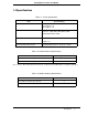
Table 1-4. DB-9 Serial Connectors, Port 0, RS232 Configuration
Pin
Port 0
(Left Port)
1CD
2RX
3TX
4DTR
5GND
6DSR
7RTS
8CTS
9RI
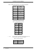
Table 1-5. RJ45 Ethernet Connector
Pin Signal
1TX +
2TX -
3---
4---
5---
6---
7RX +
8RX -
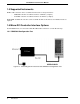
✎ Note The power input is a standard 2.1 mm P5 type input jack. The
center is positive, and the outer shell is negative.
Table 1-6. Power Connector
Pin Signal
Center 7 - 30 V dc
Shell GND