
Manual

EP1000A E-Port Instruction Manual
20 Installation
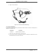
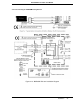
2.4.1.2 Power Adapter Cable Connection (Optional)
1. On the RS232/485 ITB, locate TB1.
2. Using the Power Adapter Cable, connect the wire labeled “+” to the terminal labeled +24 on
TB1.
3. Using the Power Adapter Cable, connect the wire labeled “-” to the terminal labeled with the
Ground symbol on TB1.
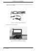
4. Using the Power Adapter Cable, connect the power input plug to the E-Port unit.
5. Using the Power Adapter Cable, connect the power jack to the power input plug of the
standard ac to dc Power Converter/Cable.
6. Using the standard power cable, connect the two-prong transformer plug into the appropriate
power source.
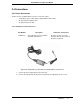
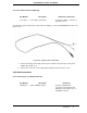
Part Number Description Comments / Instructions
677C101U01
Power Adapter Cable, 12-30 V dc Provides the ability to power both
an ITB and the E-Port Unit using
the standard power cable. Can be
connected to either the standard
ac power cable, or the optional dc
power cable.
Figure 2-7. Power Adapter Cable