INSTRUCTION MANUAL EP1000A E-Port Ethernet Interface Port for Micro-DCI® DataLink and Modbus PN26010, Rev.
MicroMod Automation, Inc. The Company MicroMod Automation is dedicated to improving customer efficiency by providing the most cost-effective, application-specific process solutions available. We are a highly responsive, application-focused company with years of expertise in control systems design and implementation. We are committed to teamwork, high quality manufacturing, advanced technology and unrivaled service and support.
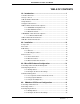
EP1000A E-Port Instruction Manual TABLE OF CONTENTS 1.0 - Introduction .......................................................................... 1 1.1 Product Overview .......................................................................................... 1 1.2 Scope of Book ............................................................................................... 1 1.3 Model Number Breakdown ............................................................................ 2 1.4 Specifications.........
EP1000A E-Port Instruction Manual 4.4 Network Management ................................................................................. 47 5.0 - Maintenance ....................................................................... 49 5.1 Parts List......................................................................................................
EP1000A E-Port Instruction Manual 1.0 Introduction 1.1 Product Overview The MicroMod Automation EP1000A E-Port product provides an interface between the serial networks used by MicroMod controllers and an Ethernet network. E-Ports with Rev. 0 firmware support the Micro-DCI Datalink protocol and can be used with Micro-DCI System Version 4.1 software products E-Ports with Rev. 1 firmware support both the Micro-DCI Datalink and MicroMod Extended Modbus.and are compatible with Micro-DCI System Version 4.
EP1000A E-Port Instruction Manual 1.3 Model Number Breakdown Refer to the MicroMod data sheet or data tag for the model number of the product furnished.
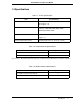
EP1000A E-Port Instruction Manual 1.4 Specifications Table 1-1. E-Port Specifications Item Specification(s) Power Requirements 7- 30 V dc 200 mA @ 12 V dc 100 mA @ 24 V dc Serial Communication RS485, four wire, asynchronous; baud rates: 1200, 2400, 4800, 9600, 19200, 28800,38400,57600,115200 Physical Characteristics Dimensions: 4.2” x 3” Weight: 5 oz. Environmental Characteristics Operating Temperature: 0 - 50°C (32 - 122°F) Table 1-2. Datalink Network Specifications Item Specification Max.
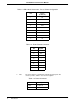
EP1000A E-Port Instruction Manual Table 1-4. DB-9 Serial Connectors, Port 0, RS232 Configuration Pin Port 0 (Left Port) 1 CD 2 RX 3 TX 4 DTR 5 GND 6 DSR 7 RTS 8 CTS 9 RI Table 1-5. RJ45 Ethernet Connector ✎ Note Pin Signal 1 TX + 2 TX - 3 --- 4 --- 5 --- 6 --- 7 RX + 8 RX - The power input is a standard 2.1 mm P5 type input jack. The center is positive, and the outer shell is negative. Table 1-6.
EP1000A E-Port Instruction Manual Table 1-7. LEDs Item Description Power LED Illuminated while power is applied.
EP1000A E-Port Instruction Manual 1.5 Supported Instruments All Micro-DCI controllers can be used with the E-Port unit. For best performance: • 53MC5000 controllers should have Revision 5 firmware (or higher). • 53 SL6000 controllers should have Revision 15 firmware (or higher). All Mod30ML and Modcell controllers can be used with the E-Port Unit. At least one Modbus interface is required. 1.
EP1000A E-Port Instruction Manual 1.6.2 53SL6000 RS-232 Port Figure 1-2. Connecting the E-Port Unit to the 53SL6000 RS232 Port 1.6.3 DataLink Network Figure 1-3.
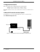
EP1000A E-Port Instruction Manual 1.7 MOD30ML / Modcell Interface Options 1.7.1 4 WIre RS-485 Modbus Figure 1-4.
EP1000A E-Port Instruction Manual 1.8 Micro-DCI Network Architecture Figure 1-5. Connecting the E-Port Unit to the DataLink Network A Micro-DCI network is a named network of up to 32 instruments. Each Micro-DCI network in the plant must have a unique name. Each network is controlled by a Master Comm Services Node and an optional Backup Comm Services Node. Each Micro-DCI network has a Network Type.
EP1000A E-Port Instruction Manual Figure 1-6. Typical System Architecture Figure 1-7.
EP1000A E-Port Instruction Manual Figure 1-8.
EP1000A E-Port Instruction Manual 1.9 Modbus Network Architecture A Modbus network is an RS485 network of up to 32 devices. Redundant communication configurations may have two E-ports per network. Figure 1-9 through Figure 1-10 illustrate possible network architectures. Figure 1-9. Typical System Architecture Figure 1-10.
EP1000A E-Port Instruction Manual 2.0 Installation 2.1 Inspection An itemized list of all items in the shipment is attached to the shipping container. Inspect the equipment upon arrival for damage that may have occurred during shipment. All damage claims should be reported to the responsible shipping agent before installation is attempted. If damage is such that faulty operation is likely to result, the MicroMod Automation Service Department should be notified.
EP1000A E-Port Instruction Manual 2.3.2 Mounting Procedures 2.3.2.1 Wall Mounting If wall/DIN rail mounting brackets were specified when the E-Port unit was ordered, the following items are supplied for mounting the unit: Part Number 122C100U01 Description Mounting hardware package, bagged. This includes: 1 pair (left and right) of aluminum brackets, black 1 pair (identical) of DIN rail clips 4 screws To fasten the E-Port unit to a wall or other flat surface, use this procedure.
EP1000A E-Port Instruction Manual 1. Verify that you have both a left and right aluminum bracket. (Place them side by side, with the flanges pointing away from each other. The tops of the center screw holes in the flanges should be pointing in the same direction (Figure 2-1). Figure 2-1. Aluminum Mounting Brackets (Pair) 2. Using two of the screws provided, attach a DIN rail clip to the flange on one of the brackets. 3. Align the second DIN rail clip so that it matches the first clip.
EP1000A E-Port Instruction Manual 4. Use the remaining two screws to attach the second clip to the flange of the second bracket. These assemblies should appear as illustrated in Figure 2-2. Figure 2-2. DIN Rail Mounting Bracket Assemblies 5. On the E-Port unit, remove the two screws on one side. 6. With the bracket flange facing away from the E-Port unit, align the screw holes in the mounting bracket with the screw holes in the side of the E-Port unit. 7.
EP1000A E-Port Instruction Manual 9. Clip the unit to the DIN rail. Figure 2-3. E-Port Unit in DIN Rail Mounting 2.3.2.3 Snap Track Mounting If a Snap Track mounting bracket was specified when the E-Port Unit was ordered, the following items are supplied for mounting the unit: Part Number 623B600U01 Description 1 aluminum Snap Track bracket 1. Remove the screws from both sides of the E-Port unit. 2.
EP1000A E-Port Instruction Manual 3. Place the screws through the holes in the brackets and unit sides, and tighten them. The unit will be fastened in the bracket. Figure 2-4. E-Port Unit in Snap Track Mounting 4. Snap the bracket into the Snap Track. Figure 2-5.
EP1000A E-Port Instruction Manual 2.4 Connections 2.4.1 Power Connections The E-Port unit is available with these power connection options: • A standard ac power cable (always supplied with an E-Port unit). • An optional power adapter cable. • An optional dc power cable. 2.4.1.
EP1000A E-Port Instruction Manual 2.4.1.2 Power Adapter Cable Connection (Optional) Part Number 677C101U01 Description Power Adapter Cable, 12-30 V dc Comments / Instructions Provides the ability to power both an ITB and the E-Port Unit using the standard power cable. Can be connected to either the standard ac power cable, or the optional dc power cable. Figure 2-7. Power Adapter Cable 1. On the RS232/485 ITB, locate TB1. 2.
EP1000A E-Port Instruction Manual 2.4.1.3 dc Power Connection (Optional) Part Number 677C100U01 Description Power Cable, optional, dc Comments / Instructions Provides the ability to connect to a dc power source. The optional dc power cable (Figure 2-8) provides the ability to connect the EP1000A E-Port unit to a dc power source. Figure 2-8. Optional dc Power Cable 1. Connect the P5-type power plug of the dc power cable into the power jack of the power adapter cable (Figure 2-7). 2.
EP1000A E-Port Instruction Manual Figure 2-9. E-Port-to-53SL6000 Connection Cable 2.4.2.2 Connecting to the Front Port of an MC5000 Unit Part Number 698B184U01 Description Cable, MC5000 front port Comments Provides a data connection from the E-Port unit RS232 port to the front data port on a 53MC5000 controller. Figure 2-10.
EP1000A E-Port Instruction Manual 2.4.2.3 Connecting to an RS-485 ITB The E-Port is connected to the RS232 ITB by a standard DB-9 null modem cable. Part Number Description Comments 172M100U01 Cable, RS232 1’ Null Modem Cable (9 pin to 9 pin) Provides a data connection from the E-Port unit RS232 port to the RS232 port on a ITB. 172M100U02 Cable, RS232 6’ Null Modem Cable (9 pin to 9 pin) Provides a data connection from the E-Port unit RS232 port to the RS232 port on a ITB. Figure 2-11.
EP1000A E-Port Instruction Manual 2.4.2.4 Connecting the RS485 ITB to Micro-DCI Controllers DataLink is an interrogator/responder (sometimes referred to as “master/slave”) serial interface capable of supporting 32 instruments on a single network. It uses an RS485 physical interface. The DataLink wiring diagram for this instrument is provided as Figure 2-12. Figure 2-12.
EP1000A E-Port Instruction Manual 2.4.2.5 Connecting to a MOD30ML using RS-232 Figure 2-13.
EP1000A E-Port Instruction Manual 2.4.2.6 Connecting to MOD30MLs using 4 wire RS-485 Figure 2-14.
EP1000A E-Port Instruction Manual 2.4.2.7 Connecting to a MODCELL using RS-232 Figure 2-15.
EP1000A E-Port Instruction Manual 2.4.2.8 Connecting to MODCELLs using 4 wire RS-485 Figure 2-16.
EP1000A E-Port Instruction Manual 2.4.3 Ethernet Network Connection 2.4.3.1 Ethernet Network Considerations Since E-Port networks are high-performance, realtime networks, the following considerations should be observed when designing your network. 2.4.3.1.1 Installation Requirements • All E-Ports and their associated PCs must be on the same subnet; that is, no routers can be used between E-Ports and their associated PCs.
EP1000A E-Port Instruction Manual 30 Installation
EP1000A E-Port Instruction Manual 3.0 Micro-DCI Software Configuration 3.1 Creating an E-Port Network with Super32 An E-Port Unit is a network interface device used to facilitate data communication between MicroMod Automation controllers and Communications Services nodes on an E-Port type network. Before you can use E-Port units, you must have an E-Port network available. E-Port communication is only available on Version 4.1 (or later) of the Micro-DCI Communication Services software.
EP1000A E-Port Instruction Manual 4. On the Network Wizard window, click on the E-Port radio button, then click Next. The Network Attributes window (Figure 3-2) is displayed. Figure 3-2. Network Attributes Window 5. In the Network Attributes pane, locate the Network Name entry box and enter the name to be used for the E-Port network. The name can be up to 9 characters in length.
EP1000A E-Port Instruction Manual 6. Click Next. The Network Mode selection window (Figure 3-3) is displayed. Figure 3-3. Network Mode Selection Window 7. Choose the mode for the Communications Services node which was selected in Step 2. Available modes are Standalone, Master, and Backup. 8. Click Next. The Finish window is displayed. The Finish window provides a summary of the configuration performed for the E-Port network. 9. Click Finish to complete the E-Port network configuration.
EP1000A E-Port Instruction Manual 3.2.2.1 Configuring the E-Port Unit IP Address If the network to which the E-Port is connected has a DHCP server running, then the values in the left pane in the window will be zero, and the IP address assigned by the DHCP server will appear in the Select a Unit pane as shown below. Figure 3-4. E-Port Setup Window If there is no DHCP server running, you must assign a static IP address. See Section 3.2.2.7, How to Choose an IP Address, below.
EP1000A E-Port Instruction Manual 3.2.2.2 Configure E-Port Unit Parameters Click the Configure E-Port button. This will open up the default web browser, to display the home page for your E-Port Unit. Figure 3-5.
EP1000A E-Port Instruction Manual 3.2.2.3 Assign Device Information to the E-Port Unit In the E-Port Name entry box, enter a device name of up to 16 characters in length for this E-Port unit. In the Description entry box, enter a description up to 60 character long for this E-Port unit. 3.2.2.4 Configure Serial Port/Network Settings for the E-Port Unit In the Serial Port Settings portion of the window, locate the Network Name entry box.
EP1000A E-Port Instruction Manual You should use one of the following address ranges, that have been reserved for use by isolated networks if you are creating an isolated network. The first range will be used for all of the examples in the documentation. 10.0.0.0 to 10.255.255.255 Class A 172.16.0.0 to 172.31.255.255 Class B 192.168.0.0 to 192.168.255.255 Class C For example: • Set Your PC’s Network Adapter Card IP Address to 10.1.1.
EP1000A E-Port Instruction Manual 3.3.2 Using Super32 Statistics Click on the Comm Stats View toolbar button. The network Comm[unications] Stat[istic]s View window will be displayed for all Micro-DCI networks. Figure 3-7. Super32 Statistics Display 3.3.3 Using E-Port Diagnostics To view communications statistics for an E-Port unit, click on the Diagnostics option located at the bottom of the E-Port Configuration web page (Figure 3-5). The statistics will be shown in the resulting display (Figure 3-8).
EP1000A E-Port Instruction Manual Figure 3-8. E-Port Statistics Display The Communication Counters provide the following data: Total DataLink Transactions The total number of transactions performed on the EPort’s DataLink since the E-Port was powered up. Total DataLink Errors The total number of errors on the E-Port’s DataLink since the E-Port was powered up. DataLink errors indicate a problem in the network wiring or the instrument’s DataLink.
EP1000A E-Port Instruction Manual 40 Configuration Parameters
EP1000A E-Port Instruction Manual 4.0 XModbus OPC Server Configuration 4.1 Creating an Ethernet Port To create an Ethernet Port: 1. From the Windows task bar, select the sequence Start > Programs > MicroMod Automation > XMBOPC > XModbus OPC Server. 2. Click the Edit menu on the menu bar. A menu is displayed.(Figure 4-1 3. Select the Ethernet Ports option on the menu. The Modbus TCP Ports Dialog (Figure 4-2) will be displayed. Figure 4-1.
EP1000A E-Port Instruction Manual 4. Click the FInd Ports button and each E-Port on the network will be listed. Figure 4-2. Modbus TCP Ports Dialog 5. Click OK to close the dialog 4.2 Creating a Device To create a new XModbus device in the OPC Server 1. Click the New XModbus Device button on the toolbar Figure 4-3.
EP1000A E-Port Instruction Manual Figure 4-4. 2. Assign a suitable name to the device 3. Sel;ect the E-Port that is wired to the device from the Port dropdown menu 4. Choose a timeout based on the devices response time. This is the time that the OPC server will wait for a response from the E-Port. If the OPC Server is the only application accessing the E-Port, a Timeout value of 100ms should be used.
EP1000A E-Port Instruction Manual 4.3 Configuring the E-Port 4.3.1 Getting Started To run the E-Port setup program: 1. Start the XModbus OPC Server and click the Tools menu on the menu bar. 2. Select Configure E-Ports to launch the E-Port setup program. 4.3.2 Configure the E-Port Unit Settings The E-Port setup program will allow you to view your E-Port unit's current settings, or modify the settings. 4.3.2.
EP1000A E-Port Instruction Manual 4.3.2.2 Configure E-Port Unit Parameters Click the Configure E-Port button. This will open up the default web browser, to display the home page for your E-Port Unit. Figure 4-6.
EP1000A E-Port Instruction Manual 4.3.2.3 Assign Device Information to the E-Port Unit In the E-Port Name entry box, enter a device name of up to 16 characters in length for this E-Port unit. In the Description entry box, enter a description up to 60 character long for this E-Port unit. 4.3.2.4 Configure Serial Port/Network Settings for the E-Port Unit In the Serial Port Settings portion of the window, locate the Network Name entry box.
EP1000A E-Port Instruction Manual 10.0.0.0 to 10.255.255.255 Class A 172.16.0.0 to 172.31.255.255 Class B 192.168.0.0 to 192.168.255.255 Class C For example: • Set Your PC’s Network Adapter Card IP Address to 10.1.1.10 (only change the Network Adapter Card, do not change your Dial-Up Adapter settings) • Set the IP address of the E-Port to 10.1.1.11 • Set the network mask for both the PC network adapter and the E-Port board to 255.255.255.0 4.
EP1000A E-Port Instruction Manual The Communication Counters provide the following data: Total Transactions The total number of transactions performed on the EPort’s Modbus since the E-Port was powered up. Total Errors The total number of errors on the E-Port’s Modbus since the E-Port was powered up. Errors indicate a problem in the network wiring or the instrument’s Modbus hardware.
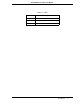
EP1000A E-Port Instruction Manual 5.0 Maintenance 5.1 Parts List The parts list is provided in Table 5-1. Table 5-1.
EP1000A E-Port Instruction Manual 50 Maintenance
The Company’s policy is one of continuous product improvement and the right is reserved to modify the information contained herein without notice, or to make engineering refinements that may not be reflected in this bulletin. Micromod Automation assumes no responsibility for errors that may appear in this manual. © 2006 MicroMod Automation, Inc. MicroMod Automation, Inc. 75 Town Centre Drive Rochester, NY USA 14623 Tel. 585-321-9200 Fax 585-321-9291 www.micromodautomation.