Micro-DCI Single-Loop Controller 53SL5100B Instruction Manual
53SL5100B Single-Loop Controller INSTRUCTION MANUAL MicroMod Automation & Controls, Inc. The Company MicroMod Automation & Controls is dedicated to improving customer efficiency by providing the most cost-effective, application-specific process solutions available. We are a highly responsive, application-focused company with years of expertise in control systems design and implementation. We are committed to teamwork, high quality manufacturing, advanced technology and unrivaled service and support.
53SL5100B Single-Loop Controller INSTRUCTION MANUAL 1 INTRODUCTION ......................................................................................................................................... 1 1.1 1.2 2 PRODUCT OVERVIEW .............................................................................................................................. 1 SPECIFICATIONS ..................................................................................................................................
53SL5100B Single-Loop Controller INSTRUCTION MANUAL 10 10.1 10.2 10.3 10.4 11 11.1 11.2 11.3 11.4 11.5 11.6 11.7 12 12.1 12.2 12.3 12.4 12.5 12.6 INSTRUMENT TUNING ......................................................................................................................... 71 PROPORTIONAL ACTION (PB)................................................................................................................. 71 INTEGRAL ACTION (TR).............................................................
3SL5100B Single-Loop Controller INSTRUCTION MANUAL IMPORTANT NOTICE All software, including design, appearances, algorithms and source code is copyrighted by MicroMod Automation & Controls, Inc. and is owned by MicroMod or its suppliers.
53SL5100B Single-Loop Controller INSTRUCTION MANUAL 1 INTRODUCTION 1.1 Product Overview The 53SL5100 Controller is capable of functioning as any one of four selectable application-specific instruments. The instrument application is selected with the front panel push buttons by entering the appropriate number (1 through 4 respectively) into a designated database location. The four instrument selections are: 1.
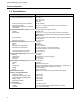
53SL5100B Single-Loop Controller INSTRUCTION MANUAL 1.2 Specifications Item Power Range (as specified in model number) Power Consumption (ac/dc operation) Internal Power Supply: Available Power Output for Transmitters Output Ripple Specification(s) 22 - 26 V dc 108 - 132 V rms 216 - 264 V rms 50/60 Hz 36 VA maximum 25 V dc ± 1 V dc @ 80 mA maximum, short circuit protected.
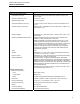
53SL5100B Single-Loop Controller INSTRUCTION MANUAL Item Environmental Characteristics Controlled Environment Specification(s) Enclosed temperature controlled location (Class A and B per ISAS71.01 1985) Ambient Temperature Limits 4 -52°C (40 - 125°F) Relative Humidity Limits 10 - 90% maximum Temperature Effects on Accuracy ± 0.28% per 28°C (50°F) change from reference temperature 25°C (77°F) Transient Immunity (all circuits) ANSI C37.90a - 1974/IEEE Std 472-974: Ring Wave: 1.
53SL5100B Single-Loop Controller INSTRUCTION MANUAL 4
53SL5100B Single-Loop Controller INSTRUCTION MANUAL 2 INSTALLATION 2.1 Inspection A list of all items in the shipment is attached to the shipping container. Inspect the equipment upon arrival for damage that may have occurred during shipment. All damage claims should be reported to the responsible shipping agent before installation is attempted. If damage is such that faulty operation is likely to result, the MicroMod Customer Service Department should be notified.
53SL5100B Single-Loop Controller INSTRUCTION MANUAL 2.3.2 Mounting Procedure For single and multiple case mounting the instruments are furnished with a trim collar (mounting frame). Figure 2-2 illustrates the installation and use of the trim collar (mounting frame). Trim collars (mounting frames) are available in various sizes and are supplied to conform with the particular panel cut-out. NOTE: Mounting brackets and trim collars (mounting frames) are packaged separately.
53SL5100B Single-Loop Controller INSTRUCTION MANUAL NOTES: 1. DIMENSIONS ARE IN INCHES. DIMENSIONS IN BRACKETS ( ) ARE IN MILLIMIETERS. 2. DIMENSIONS GUARANTEED ON CERTIFIED PRINTS ONLY. 3. CASE MOUNTING HARDWARE SUPPLIED UNLESS OTHERWISE SPECIFIED. 4. THIS DRAWING IS THIRD-ANGLE PROJECTION AS SHOWN 5. UNLESS OTHERWISE INDICATED ALL TOLERANCES ARE ± 1/16 (1.6) Figure 2.
53SL5100B Single-Loop Controller INSTRUCTION MANUAL Figure 2-2. Single or Multiple Panel Mounting Figure 2-3.
53SL5100B Single-Loop Controller INSTRUCTION MANUAL 2.4 Power & Signal Wiring PREPARATORY: The 53SL5100 can be configured for one to four analog inputs (ANI0-3), one analog output (ANO0), two control contact inputs (CCI0 and 1), two control contact outputs (CCO0 and 1) and Datalink network interconnectivity. Therefore, prior to making electrical connections, the particular instrument configuration should be determined with all assigned inputs and outputs identified to assure proper signal routing.
53SL5100B Single-Loop Controller INSTRUCTION MANUAL Figure 2-4.
53SL5100B Single-Loop Controller INSTRUCTION MANUAL Figure 2-5.
53SL5100B Single-Loop Controller INSTRUCTION MANUAL 2.4.1 Power Wiring Refer to the instrument model number to verify the power input requirements: 53SL511…. – AC Power 53SL512…. – DC Power 2.4.1.1 DC Power Reference Figure 2-4 and connect the remote 24 V dc power supply to the instrument as follows: 1. Connect (+) input line, via remote SPST switch, to terminal L1. 2. Connect (-) input line to the system bus bar. The bus bar should be connected to a good earth ground (#8 AWG wire is recommended).
53SL5100B Single-Loop Controller INSTRUCTION MANUAL 2.4.3 Datalink Communication Datalink is an interrogator/responder serial interface capable of supporting 32 instruments on a single network. It uses an RS485 physical interface. The Datalink wiring diagram for this instrument is provided as Figure 2-5. Complete coverage of the Datalink is provided in Instruction Bulletin 53SU5000. 2.
53SL5100B Single-Loop Controller INSTRUCTION MANUAL 14
53SL5100B Single-Loop Controller INSTRUCTION MANUAL 3 FRONT PANEL The front panel of the instrument contains the display and all push buttons used to change display presentations and parameters. The front panel has a gas discharge 96 X 48 dot matrix display, a six pushbutton vertical keypad, and a four pushbutton horizontal keypad. It also has a configuration port DIN plug, which is concealed behind the identification tag pull-down door. To open this door, press on the lower front edge.
53SL5100B Single-Loop Controller INSTRUCTION MANUAL The three bar graph display types for CS1-4 and the parameter display, with appropriate call outs, are illustrated in Figure 3-2 through Figure 3-5. Figure 3-6 and Figure 3-7 illustrate displays with alarm and configuration overlays. Figure 3-2. CS1, Single Loop PID Controller or CS2, Analog Backup Controller Figure 3-3.
53SL5100B Single-Loop Controller INSTRUCTION MANUAL Figure 3-4. CS4, Automatic/Manual Station Figure 3-5.
53SL5100B Single-Loop Controller INSTRUCTION MANUAL Figure 3-6. Alarm Overlay Figure 3-7.
53SL5100B Single-Loop Controller INSTRUCTION MANUAL 3.2 Front Panel Pushbuttons The front panel pushbuttons are used to vary the display presentation, to select instrument operator or engineering modes, and to select local or remote setpoint levels. In engineering mode, (EMODE) they are also used to display and/or alter database parameters which are presented as single line datapoints in the configuration overlay.
53SL5100B Single-Loop Controller INSTRUCTION MANUAL Pushbutton Title Remote/ Local Select F1, F2 F3 Setpoint Increase (EMODE Character Select) The setpoint indicator increases (rises) when this pushbutton is pressed and held. Release the pushbutton when the desired setpoint level is reached. This pushbutton is for Local operation only. Setpoint Decrease (EMODE Character Select) The setpoint indicator decreases (falls) when this push button is pressed and held.
53SL5100B Single-Loop Controller INSTRUCTION MANUAL 3.3 Displaying a Datapoint The following procedure illustrates how to enter Engineering Mode (EMODE) and use the display function to access the contents of datapoint A001 (A1). The displayed contents will be PERCENT. Figure 3-9 and Figure 3-10 are supporting illustrations for the display procedure which is described in Table 3-2. It should be noted that EMODE has a 20 second timeout if it is accessed and its functions (e.g.
53SL5100B Single-Loop Controller INSTRUCTION MANUAL 3.4 Altering a Datapoint The following procedure illustrates how to enter EMODE and use the configuration function to alter the contents of datapoint B000 (B0) with a 97. Entering a 97 in B00 invokes the display test which strobes the display matrix dots on and off at 5 second intervals (approximate). When off, a perimeter of dots still remains lit. Figures 3-11 and 3-12 are display test illustrations that support the procedure provided in Table 3-3.
53SL5100B Single-Loop Controller INSTRUCTION MANUAL Figure 3-11. Checkerboard Pattern Figure 3-12. Permiter Dots Illuminated 3.5 Defaulting the Database Defaulting the database sets all non-instrument-specific datapoint parameters to predetermined values, then suspends the instrument which is indicated by the logo presented on the display. When instrument operation is suspended, instrument algorithmic control ceases.
53SL5100B Single-Loop Controller INSTRUCTION MANUAL Table 3-4. Defaulting the Database Step 1 Press Once Shift Result Result MODE If DISPLAY appears instead of CONFIGURE press F2. Displays entry line: POINT . (If the prompt KEY? appears, see Table 3-5.) F3 4 B Puts B on entry line: POINT .B. 5 .BΔ 0 Shifts B and puts 0 on entry line: POINT .B0. 6 .B0Δ 0 Shifts B0 and puts 0 on entry line: POINT .B00. 7 8 Displays contents of B00 (0). F3 Hold .
53SL5100B Single-Loop Controller INSTRUCTION MANUAL 3.6 Responding to the Prompt: KEY? When the password prompt KEY? appears, it indicates a password was set in the MicroTools software. The password can not be set via the front panel push buttons. A password key is a maximum of 10 numeric characters (numbers 0-9 only). It does not impede display functions in engineering mode but must be unlocked to perform configuration functions.
53SL5100B Single-Loop Controller INSTRUCTION MANUAL 26
53SL5100B Single-Loop Controller INSTRUCTION MANUAL 4 CONFIGURATION PARAMETERS The configuration parameters provide the latitude to define the instrument’s personality attributes, so that while still functioning within its designed specifications, it can perform application requirements with greater refinement. Typical configuration parameters are the instrument’s indicator zero point and span, the display tag names, engineering units of the displayed process value, and alarm limits, etc.
53SL5100B Single-Loop Controller INSTRUCTION MANUAL If the state of the database is unknown, the instrument can be returned to the factory standard configuration with two datapoint entries: 1. Set B00 to 98 to default the database. 2. Set B00 to 1 to start functioning as a Single Loop Controller. If the unit is to be operated online, it must be installed as described in Section 2, Installation. ANI0 (PV Input) and ANO0 (Output) must be connected, and the unit must have power applied. 4.
53SL5100B Single-Loop Controller INSTRUCTION MANUAL Table 4-4. Analog Input (ANI) Module Purpose: This module is used to configure input voltage characteristics (e.g., input voltage range), and how the input signals are interpreted (linear or square root representation). ANI0 ANI1 Title Symbol Datapi Default Attributes Datapoint nt Analog This is the value in engineering units of the Input ANI H000 H001 0 measured input after all signal conditioning has (Display been applied.
53SL5100B Single-Loop Controller INSTRUCTION MANUAL Figure 4-1. ANI0-3 Figure 4-2. ANO0 NOTE: These figures are graphical representations of the signal conditioning that occurs on the instrument main board. They are provided for reference purposes only. Table 4-5. Analog Output (ANO) Module Purpose: The primary purpose of this module is to set the 0 - 20 mA output signal relative to the displayed percent and to select the analog input signal (ANI0-3) that is to be routed to the analog output (ANO0).
53SL5100B Single-Loop Controller INSTRUCTION MANUAL Table 4-7. Contact Output Module (CCO) Purpose: This module allows the action of the CCO to be reversed (normally a closed contact = 1, but can be changed to = 0). Title Symbol Data-point Default Attribute If CCO = 0 and OINV = 0, then it is open. Contact Output If CCO = 0 and OINV = 1, then it is closed. CCO L024 0 (Display If CCO = 1 and OINV = 0, then it is closed. Only) If CCO = 1 and OINV = 1, then it is open.
53SL5100B Single-Loop Controller INSTRUCTION MANUAL Table 4-8. Control Module Purpose: The primary purpose of this module is to set the instrument’s responsiveness, Alarm Limits 1 & 2, Alarm Dead Band, and the range limits (e.g., 0 - 100, -20 - 80, etc.). Note: ■= applicable to the Control Strategy (CS) as shown in column three.
53SL5100B Single-Loop Controller INSTRUCTION MANUAL Table 4-8. Control Module (continued) Purpose: The primary purpose of this module is to set the instrument’s Alarm Index mode, Alarm Limits 1 & 2, and Alarm Dead Band. CS Title Symbol ■ 1|2|3|4 CON-0 Datapoint Default 106 0 When set to a 0, the controller output increases as the process value increases. When set to a 1, the controller output decreases as the process value increases.
53SL5100B Single-Loop Controller INSTRUCTION MANUAL Table 4-9. Parameter Display Module Purpose: This module provides quick pushbutton display access to any three selected datapoints (e.g., Alarm Limits 1 & 2 and Alarm Dead Band) without the necessity of entering Engineering mode and addressing the datapoints. Title Symbol PAR1 Default Attribute This is an assignable in character name that appears CON-0 PTAG A014 Title TUNE with the parameter display.
53SL5100B Single-Loop Controller INSTRUCTION MANUAL Table 4-10. Communication Module Purpose: This module is used to configure the Datalink port parameters (e.g., baud rate, parity selection, etc.). Title Symbol Datapoint Default Attribute Instrument Address IA B01 0 It identifies the address of this instrument on the Datalink network. Each unit connected to the Datalink network must have its own unique address. Valid addresses are from 0 -31.
53SL5100B Single-Loop Controller INSTRUCTION MANUAL Table 4-11. System Module Purpose: This module is used to set the instrument tag name and the display brightness. System Title Symbol Module Default Attribute Datapoint The operational algorithm of the unit is selected by the value of this parameter: 0 = Suspend mode. No control algorithm execution. The logo is displayed. 1 = CS1, Single Loop PID Controller operation 2 = CS2, Analog Backup Controller operation.
53SL5100B Single-Loop Controller INSTRUCTION MANUAL 5 SINGLE LOOP (PID) CONTROLLER 5.1 Operation Overview In a standard feedback control loop, the Single Loop (PID) Controller functions as the primary processing unit. When the process is altered due to disturbances (e.g., flow rate changes), the controller gauges this change from the process variable (PV) feedback signal sent to it by a process measurement instrument (e.g., flow meter) in the loop.
53SL5100B Single-Loop Controller INSTRUCTION MANUAL It is the difference between the setpoint (SP) and received process variable (PV), augmented by the action of the tuning constants Proportional Band, Reset Time, and Rate Time, that determines the required output to the final element to restore the process. The output signal (Analog Output) to the final element is 4-20 mA dc. This signal is also factory calibrated for zero and span, and should not be altered.
53SL5100B Single-Loop Controller INSTRUCTION MANUAL Figure 5-2.
53SL5100B Single-Loop Controller INSTRUCTION MANUAL 5.2 Single Loop Controller Front Panel Pushbuttons The front panel pushbuttons for the Single Loop Controller are illustrated in Figure 5-3 and defined in Table 51. The pushbutton functions for the Single Loop Controller are identical to those provided in Section 3. Figure 5-3.
53SL5100B Single-Loop Controller INSTRUCTION MANUAL Table 5-1. Controller Pushbuttons Pushbutton Title Remote/ Local Select F1, F2 F3 Operator Mode Used to select between Remote setpoint control and Local setpoint control. When in Remote, an R appears in the lower right of the display. When in Local, an L appears in the lower right of the display. Setpoint Increase (EMODE Character Select) The setpoint indicator increases (rises) when this pushbutton is pressed and held.
53SL5100B Single-Loop Controller INSTRUCTION MANUAL instrument between Operator mode and Engineering mode. 5.3 Single Loop Controller Parameter Selections Figure 5-4 illustrates how a Single Loop Controller would appear with only the default values and power applied, but no analog input or output signals. In Figure 5-5, ANO0 (TB1-10) is jumpered to ANI0 (TB1-2) to simulate process operation. The unit has the AC power supply and power cord 173D109U03.
53SL5100B Single-Loop Controller INSTRUCTION MANUAL 5.3.1 Abbreviated Configuration Tables Table 5-1 through Table 5-8 are provided as a quick reference source for the contiguration datapoints. These tables do not have the definition column; therefore, for the initial instrument configuration, Section 4 should be referenced until each datapoint functionality can be recognized by its title.
53SL5100B Single-Loop Controller INSTRUCTION MANUAL Table 5-6.
53SL5100B Single-Loop Controller INSTRUCTION MANUAL 6 ANALOG BACKUP CONTROLLER 6.1 Analog Backup Controller Operation Overview The Analog Backup Controller is used in operations where a remote computer is normally controlling the final element directly. In this process configuration, the controller functions as a signal selector and automatic backup unit to the computer. The controller assumes process control in the event of a signaled computer failure.
53SL5100B Single-Loop Controller INSTRUCTION MANUAL As illustrated in Figure 6-2, Analog Backup Controller Block Diagram, when a 2 is loaded into System Module datapoint B00 to indicate CS2, the signal designators are as follows: 1. ANI0 = Process Variable 2. ANI1 = Control Element Feedback 3. ANO0 ~ Controller Output 4. CCI0 = Computer Ready 5. CCO0 = Computer Output Diverter 6. CCO1 = Backup Output Diverter Figure 6-2.
SL5100B Single-Loop Controller INSTRUCTION MANUAL 6.2 Analog Backup Controller Front Panel Pushbuttons The front panel push buttons for the Analog Backup Controller are illustrated in Figure 6-3 and defined in Table 6-1. Figure 6-3.
53SL5100B Single-Loop Controller INSTRUCTION MANUAL Table 6-1. Controller Pushbuttons Pushbutton Title Remote/ Local Select F1, F2 F3 Setpoint Increase (EMODE Character Select) The setpoint indicator increases (rises) when this pushbutton is pressed and held. Release the pushbutton when the desired setpoint level is reached. This pushbutton is for Local operation only. Setpoint Decrease (EMODE Character Select) The setpoint indicator decreases (falls) when this push button is pressed and held.
53SL5100B Single-Loop Controller INSTRUCTION MANUAL 6.3 Analog Backup Controller Parameter Selections Figure 6-4 illustrates how an Analog Backup Controller would appear with only the default values and power applied., but no analog input or output signals. In Figure 6-4, ANO0 (TB1-10) is jumpered to ANI0 (TB1-2) to simulate process operation. The unit has the AC power supply and power cord 173D109U03.
53SL5100B Single-Loop Controller INSTRUCTION MANUAL 6.4 Abbreviated Configuration Tables Table 6-2 through Table 6-8 are provided as a quick reference source for the configuration datapoints. These tables do not have the definition column; therefore, for the initial instrument configuration, Section 4 should be referenced until each datapoint functionality can be recognized by its title.
53SL5100B Single-Loop Controller INSTRUCTION MANUAL Table 6-6.
53SL5100B Single-Loop Controller INSTRUCTION MANUAL 52
53SL5100B Single-Loop Controller INSTRUCTION MANUAL 7 RATIO (PID) CONTROLLER 7.1 Ratio (PID) Controller Operation Overview The Ratio (PID) Controller is used where one variable, called the controlled variable, must be automatically maintained in definite proportion to another variable, called the wild variable. Transmitting meters (e.g., flow meters) must be installed in each variable line.
53SL5100B Single-Loop Controller INSTRUCTION MANUAL As illustrated in Figure 7-2, Ratio (PID) Controller Block Diagram, when a 3 is loaded into System Module datapoint B00 to indicate CS3, the signal designators are as follows: 1. ANI0 = Controlled Variable 2. ANI1 = Wild Variable 3. ANO0 = Controller Output 4. CCO0 = Process Alarm Figure 7-2.
53SL5100B Single-Loop Controller INSTRUCTION MANUAL 7.2 Ratio (PID) Controller Front Panel Pushbuttons The front panel push buttons for the Ratio (PID) Controller are illustrated in Figure 7-3 and defined in Table 71. Figure 7-3.
53SL5100B Single-Loop Controller INSTRUCTION MANUAL Table 7-1. Controller Pushbuttons Pushbutton Title Operator Mode Engineering Mode Ratio/ Local Select R indicates Ratio control whereby the controller maintains a set proportion between the wild variable line and the controlled variable line. When in Ratio, an R appears in the lower right of the display. When in Local, an L appears in the lower right of the display.
53SL5100B Single-Loop Controller INSTRUCTION MANUAL toggle the instrument between Operator mode and Engineering mode. 7.3 Ratio Controller Parameter Selections Figure 7-4 illustrates how a Ratio Controller would appear with only the default values and power applied, but no analog input or output signals. In Figure 7-4, ANO0 (TB1-10) is jumpered to ANI0 (TB1-2) to simulate process operation. The unit has the AC power supply and power cord 173D109U03.
53SL5100B Single-Loop Controller INSTRUCTION MANUAL 7.4 Abbreviated Configuration Tables Table 7-2 through Table 7-7 are provided as a quick reference source for the configuration datapoints. These tables do not have the definition column; therefore, for the initial instrument configuration, Section 4 should be referenced until each datapoint functionality can be recognized by its title.
53SL5100B Single-Loop Controller INSTRUCTION MANUAL Table 7-6.
53SL5100B Single-Loop Controller INSTRUCTION MANUAL 60
53SL5100B Single-Loop Controller INSTRUCTION MANUAL 8 AUTOMATIC/MANUAL STATION 8.1 Automatic/Manual Station Operation Overview The Automatic/Manual Station is a conventional single station selector. In Auto, the auto input (Analog Input 0) is passed directly through the station to the output (Analog Output 0). In Manual, the station functions as a manual loader, allowing the output to be controlled from the front panel pushbuttons.
53SL5100B Single-Loop Controller INSTRUCTION MANUAL Figure 8-2.
53SL5100B Single-Loop Controller INSTRUCTION MANUAL 8.2 Automatic/Manual Station Front Panel Pushbuttons The front panel push buttons for the Automatic/Manual Station are illustrated in Figure 8-3 and defined in Table 8-1. Figure 8-3.
53SL5100B Single-Loop Controller INSTRUCTION MANUAL Table 8-1. Front Panel Pushbuttons Pushbutton F1, F2 F3 Title Remote/ Local Select Engineering Mode Not used Not used Setpoint Increase (EMODE Character Select) Not used Setpoint Decrease (EMODE Character Select) Not used Auto/Manual Select This pushbutton is the Auto/ Manual mode toggle. When toggled to Auto, an A appears before the R or L (for Remote or Local), in the lower middle right of the display.
53SL5100B Single-Loop Controller INSTRUCTION MANUAL 8.3 Automatic/Manual Station Parameter Selections Figure 8-4 illustrates how a Single Loop Controller might appear with only the default values and power applied, but no analog input or output signals. In Figure 8-4, ANO0 (TB1-lO) is jumpered to ANI0 (TB1-2) to simulate process operation. The unit has the AC power supply and power cord 173D109U03.
53SL5100B Single-Loop Controller INSTRUCTION MANUAL Table 7-6. Control (CON-0) Module Title Control Alarm Mode Manual Fallback Disable Alarm Limit 1 Alarm Limit 2 Alarm Dead Band Controller Span Controller Lower Range Control Tag Name Engineering Units CON-0 Datapoint Symbol AIX MFD PL1 PL2 ADB IR ILR CTAG CEU B335 L120 C103 C104 C105 C115 C116 A000 A001 Default 1 0 100 0 2 100 0 CON-0 Percent Table 8-7.
53SL5100B Single-Loop Controller INSTRUCTION MANUAL 9 PARAMETER DISPLAY The parameter display can be accessed from any control strategy (CS1 - CS4) by pressing the F1 or F2 front panel push button. It provides convenient access to view and/or alter three parameter datapoint values that were selected when the display was configured. (The option to view and alter any parameter datapoint value with EMODE is still available.
53SL5100B Single-Loop Controller INSTRUCTION MANUAL Figure 9-1.
53SL5100B Single-Loop Controller INSTRUCTION MANUAL 9.1 Parameter Display Configuration Settings Figure 9-2 is an illustration of the parmeter display with datapoint call outs. Table 9-2 is an abbreviated parameter display configuration table. Figure 9-2. Parameter Display Datapoint Selections Table 9-2.
53SL5100B Single-Loop Controller INSTRUCTION MANUAL 70
53SL5100B Single-Loop Controller INSTRUCTION MANUAL 10 INSTRUMENT TUNING Tuning the instrument is an iterative process to refine the Proportional Band (PB), Integral (also called Reset Time [TRI]), and Derivative (TD) parameters of the Control Module 0 (CON-0). The three parameter datapoints are C106, Proportional Band (PB); C107, Reset Time (TR); and C108, Derivative Time (TD).
53SL5100B Single-Loop Controller INSTRUCTION MANUAL 10.4 Instrument Tuning Table 10-1 provides summary information for the tuning parameters referenced in the three tuning methods that follow. The Trial and Error Method (Table 10-2) is usually preferred for processes that respond quickly, requiring no waiting to determine steady cycling process conditions. The Proportional Cycle Method (Table 10-3) and Step Response Method (Table 10-4) are expedient procedures for slow processes.
53SL5100B Single-Loop Controller INSTRUCTION MANUAL Table 10-1. Summary Information for Tuning Parameters Abbreviation Datapoint Min Value Max Value Parameter P.B. TR TD C106 C107 C108 2% 0.02 minutes/rep. 0.01 minutes 1000% 200 minutes/rep. 8 minutes Proportional Band Reset Rate Table 10-2. Summary Information for Tuning Parameters Step 1 2 3 4 5 6 7 8 9 10 11 Procedure Set the process to approximately normal conditions in Manual mode. Set TR (C107) first to minimum value (0.
53SL5100B Single-Loop Controller INSTRUCTION MANUAL Figure 10-1.
53SL5100B Single-Loop Controller INSTRUCTION MANUAL 11 EASY-TUNE The EASY-TUNE algorithm is used to help determine the optimal tuning values for the Proportional Band (PB), Integral (TR), and Derivative (TD) parameters (called PID constants) in the Controller Module Mode 0 (CON-0). The three parameter datapoints are C106, Proportional Band (PB); C107, Reset Time (TR); and C108, Derivative Time (TD).
53SL5100B Single-Loop Controller INSTRUCTION MANUAL 11.3 EASY-TUNE Parameters All pertinent input parameters to the EASY-TUNE algorithm are obtained from Controller Module Mode 0, which must first be configured. The parameters that must be configured before initiating the EASY-TUNE sequence (B008 = 1) are items 1, 3, 5 through 10, in Table 11-1. Table 11-1.
53SL5100B Single-Loop Controller INSTRUCTION MANUAL 11.4 EASY-TUNE Sequence Status Once initiated, the algorithm sets the instrument to Manual mode. After a period of settling time, a step change in instrument output is applied and the resulting process response is observed. As summarized in Table 11-2 and Table 11-3, datapoint 8387, EASY-TUNE Status, will numerically show the result of the EASY-TUNE algorithm. Figure 11-1 illustrates this event sequence and correlates it to the numeric codes in B387.
53SL5100B Single-Loop Controller INSTRUCTION MANUAL Figure 11-1.
53SL5100B Single-Loop Controller INSTRUCTION MANUAL 11.5 Modifications to Tuning Criteria During EASY-TUNE sequence execution, each of the three algorithm variables: Time Constant (TP ), Process Gain (KP), and Dead-Time (WP), are altered by 10% in the conservative direction, (instrument operating characteristics would be slower response, but less chance of oscillation and instability) before the tuning parameters are computed using the ITAE equations listed in Table 11-4.
53SL5100B Single-Loop Controller INSTRUCTION MANUAL Figure 11-2.
53SL5100B Single-Loop Controller INSTRUCTION MANUAL 11.6 Aborting the EASY-TUNE Sequence If the EASY-TUNE sequence is active and the instrument output is deliberately changed, the sequence will be aborted. The original instrument output and Manual or Auto mode will be restored. Datapoint B387, EASYTUNE Status, will be set to 54. If the EASY-TUNE sequence is active and datapoint L521, EASY-TUNE Abort Switch, is set to 1, the sequence is immediately aborted.
53SL5100B Single-Loop Controller INSTRUCTION MANUAL 82
53SL5100B Single-Loop Controller INSTRUCTION MANUAL 12 MAINTENANCE NOTE: The factory set calibration constants for ANI0-3 and ANO0 are applicable only for the main printed circuit board supplied in the particular instrument. This data is recorded on a calibration sheet supplied with the instrument. The data should be retained to facilitate easy field recalibration in the event one or more of the constants is inadvertently changed. 12.
53SL5100B Single-Loop Controller INSTRUCTION MANUAL DC Power: 3A, 250 V, Slow Blow BEL Type 5TT3 For additional information, contact MicroMod Automation. NOTE: When communicating with MicroMod for replacement of the main PCB, reference the unit’s serial number to ensure the correct replacement assembly is supplied. The necessary ordering information is provided on the instrument data tag and on the manufacturing specification sheet supplied with that particular controller.
53SL5100B Single-Loop Controller INSTRUCTION MANUAL If the F3 push button is pressed and held during controller reset, the controller is forced to the suspend state (FIX 0).
53SL5100B Single-Loop Controller INSTRUCTION MANUAL 12.6 Parts List The parts list is provided in Table 5-1 and the parts breakdown is illustrated in Figure 5-1. Note that these boards are for the 53SL5100 Design Level B, not the 53SL5000 Design Level A. Contact MicroMod for more information on spare parts availability for the 53SL5100A. Table 5-1.
53SL5100B Single-Loop Controller INSTRUCTION MANUAL Figure 5-1.
53SL5100B Single-Loop Controller INSTRUCTION MANUAL Figure 5-3.
53SL5100B Single-Loop Controller INSTRUCTION MANUAL 89
53SL5100B Single-Loop Controller INSTRUCTION MANUAL Appendix A: Discrete Contact Output CCO’s The discrete output CCOs are not mechanical contact closures but NPN Transistors that are analogous to single pole, single throw switches with one terminal connected to power common. This circuit type layout is commonly called an Open Collector Output. (See Figure A-1.) Capability limits of each CCO are as follows: 50 mA maximum current flow when closed. 30 V dc maximum tolerance voltage when open.
53SL5100B Single-Loop Controller INSTRUCTION MANUAL Figure A-1. CCO Circuit and its Equivalent Figure A-2.
53SL5100B Single-Loop Controller INSTRUCTION MANUAL Figure A-3. Operating CCOs in Parallel Figure A-4. CCO with Solid State Relay Figure A-5.
53SL5100B Single-Loop Controller INSTRUCTION MANUAL 93
53SL5100B Single-Loop Controller INSTRUCTION MANUAL Appendix B : Communications Two digital communication channels are provided with this instrument: RS-232 serial configuration port, accessed via a 5 pin mini-DIN connector located under the pulldown door on the front panel (see Figure 1-2). It is used to configure instrument parameters for selected operational characteristics. The parameters are configured with Micro-Tools software running on a customer supplied PC.
53SL5100B Single-Loop Controller INSTRUCTION MANUAL Table B-1. Communication Module Purpose: This module is used to configure the Datalink port parameters (e.g., baud rate, parity selection, etc.). Title Datapoint Setup Default Attribute Instrument Address B01 S 0 Baud Rate B02 S 253 No Parity L256 0 0 No Byte Stuffing L258 0 0 Datalink Disable L257 0 0 It identifies the address of this instrument on the Datalink network.
53SL5100B Single-Loop Controller INSTRUCTION MANUAL Protocol The Datalink protocol requires the host to initiate all transactions. There are two basic categories for all of the Datalink message types: Interrogate - used to read data from an addressed instrument, and Change used to alter a value in an addressed instrument. The addressed instrument decodes the message and provides an appropriate response. The protocol definitions for the Datalink message types are provided in Table B-2. Table B-2.
53SL5100B Single-Loop Controller INSTRUCTION MANUAL 4. ACKNOWLEDGE - This message signals the addressed instrument that its last echoed change message was received correctly; the instrument performs the change requested. 01111110 80H + I.A. INSTRUMENT TO HOST: 1. RESPONSE - This message furnishes the data requested by the INTERROGATE command of the Host. It is also used to echo back the previous CHANGE message of the Host. 01111110 20H + I.A.
53SL5100B Single-Loop Controller INSTRUCTION MANUAL + I.A. 4. Instrument performs the change requested at end of the current program scan.
53SL5100B Single-Loop Controller INSTRUCTION MANUAL Calculating Data Addresses If communications software must be generated to accommodate unique Datalink applications requirements, then the instrument memory address scheme must be known for proper data bit (e.g., L data type) and data byte (e.g., B, C, H, and A data types) memory location determination. NOTE: Numbers used in this section that are expressed in hexadecimal notation (base 16) are identified with an H after the number.
53SL5100B Single-Loop Controller INSTRUCTION MANUAL Table B-3. Instrument Memory Address Scheme (continued) Data Type H A (F)* Base Memory Address F00H 1400H Byte Size 5 10 (A) 5 (F)* Data Format Represents high precision floating point values that have a resolution of one part in 2 billion (31 bits) and a dynamic range of ± 1038 . The first four bytes represent a 2’s complement notation in fractional form (2-n) whose absolute value is between 0.5 and 0.9999.
53SL5100B Single-Loop Controller INSTRUCTION MANUAL Appendix C: Database The database contains five datapoint types. Each datapoint type represents a specific data format: whole integers, alphanumeric text strings, etc. The datapoint types are defined in Table C-1 and the database is listed in alphanumeric order in Table C-2. The gray-tone shading in the Symbol cell of a datapoint indicates the datapoint does not have an assigned symbol. Table C-1.
53SL5100B Single-Loop Controller INSTRUCTION MANUAL Table C-2. Database Title Control Tag Name Symbol Datapoint Default CTAG A000 CON-0 CEU A001 PERCENT TAG A008 SL5100 PTAG A014 CON-0 TUNE PNA A015 PROP.
53SL5100B Single-Loop Controller INSTRUCTION MANUAL EASY-TUNE Enable ETE B008 0 BRIGHT B012 4 ANI0 Calibrate Zero CIZ B263 ANI1 Calibrate Zero CIZ B264 ANO1 Calibrate Zero COZ B267 ANI0 Digital Filter Index DFILT B269 3 ANI1 Digital Filter Index DFILT B270 3 Display Brightness Index Control Alarm Mode AIX B335 1 Value Baud Rate Value Baud Rate 255 28800 9 28800 254 14400 8 14400 N/A N/A 7 19200 253 9600 6 9600 250 4800 5 4800 244 2400 4 2400 232 1200 3 1200 208 600 2 600 160 30
53SL5100B Single-Loop Controller INSTRUCTION MANUAL 2 B335 PV 0 >60 0 <40 2 >60 2 <40 3 >60 3 <40 4 >60 4 <70 5 >40 5 <30 6 >50 6 <30 PL1 (C103) 60 Analog Output (Display Only) PL2 (C104) 40 60 40 60 40 60 70 40 30 10 HIGH Alarm Llimit 1 is set for 60: PV > 60 = HIGH alarm LOW Alarm Limit 2 is set for 40: PV < 40 = LOW alarm HIGH Alarm Limit 1 is set for 60: PV > 60 = HIGH alarm N/A Alarm Limit 2 is set for 40: PV < 40 = no alarm N/A Alarm Limit 1 is set for 60: PV >
53SL5100B Single-Loop Controller INSTRUCTION MANUAL Reset Time TR C107 0 Rate Time TD C108 0 Manual Reset MR C111 50 Controller Span IR C115 100 Controller Lower Range ILR C116 0 Remote Setpoint RSP C120 0 ANI0 Engineering Span SPAN C256 100 ANI1 Engineering Span SPAN C257 100 ANI0 Engineering Zero ANI1 Engineering Zero ANI0 Calibrate Span ZERO C276 0 controller response in standard PID terms.
53SL5100B Single-Loop Controller INSTRUCTION MANUAL Only) CCO Output (Display Only) CCO L024 0 Control Action RSW L106 1 Auto Status AUT L107 0 Remote Status RMT L108 0 Reverse Valve RSV L109 0 Alarm A Active PA1 L110 0 Alarm B Active PA2 L111 0 Auto Switch SWA L112 0 Remote Switch SWR L113 0 Auto Enable AE L114 1 Remote Enable RE L115 0 Manual Fallback Disable MFD L120 0 CP L256 0 Datalink Disable DLD L257 0 Datalink No Byte Stuffing CB L258 0 Dat
53SL5100B Single-Loop Controller INSTRUCTION MANUAL CCI Input Invert IINV L264 0 CCO Output Invert OINV l288 0 Parameter Display Modify Disable PMD L313 0 ANI0 0 - 5 V Input NOBIAS L416 0 ANI1 0 - 5 V Input NOBIAS L417 0 ANI0 Square Root Signal SQRT L440 0 ANI1 Square Root Signal SQRT L441 0 OZBASE L472 0 ANO0 0 -20 mA Output 0 when using MicroMod communications software or equipment.
53SL5100B Single-Loop Controller INSTRUCTION MANUAL 108
The Company’s policy is one of continuous product improvement and the right is reserved to modify the information contained herein without notice, or to make engineering refinements that may not be reflected in this bulletin. MicroMod Automation & Controls, Inc. assumes no responsibility for errors that may appear in this manual. © 2004 MicroMod Automation & Controls, Inc. Printed in USA PN24469 Issue 3, April 2014 MicroMod Automation & Controls, Inc. 75 Town Centre Drive Rochester, NY USA 14623 Tel.