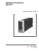
INSTRUCTION MANUAL Manual Loader 53ML5100A MANUAL LOADING STATION PN24480 Rev.
MicroMod Automation, Inc. The Company MicroMod Automation is dedicated to improving customer efficiency by providing the most ost-effective, application-specific process solutions available. We are a highly responsive, application-focused company with years of expertise in control systems design and implementation. We are committed to teamwork, high quality manufacturing, advanced technology and unrivaled service and support.
Contents Table of Contents 1.0 INTRODUCTION 1.1 1.2 1.3 1.4 PRODUCT OVERVIEW . . . . SCOPE OF BOOK . . . . . . . MODEL NUMBER BREAKDOWN SPECIFICATIONS . . . . . . . 1-1 . . . . . . . . . . . . . . . . . . . . . . . . . . . . . . . . . . . . . . . . . . . . . . . . . . . . . . . . . . . . . . . . . . . . . . . . . . . . . . . . . . . . . . . . . . . . . . . . 2.0 INSTALLATION 2.1 INSPECTION . . . . . . . . . . . . . . . . . . . . . . . . 2.2 LOCATION . . . . . . . . . . . . . . . .
53ML5100 Manual Loading Station 5.3 5.4 5.5 5.6 5.7 CALIBRATION . . . . . . . . . . . . . . . . . ERROR AND HARDWARE MALFUNCTION MESSAGES RESETTING THE INSTRUMENT . . . . . . . . . . PARTS LIST . . . . . . . . . . . . . . . . . . SUPPLEMENTAL INFORMATION . . . . . . . . . . . . . . . . . . . . . . . . . . . . . . . . . . . . . . . . . . . . . . . . . . . . . . . . . . . . . . . . . . . . . . . . . . . . . .
Section 1. Introduction 1.0 INTRODUCTION 1.1 PRODUCT OVERVIEW The 53ML5100 Manual Loading Station provides the capability to manually adjust and display one or two current outputs. Each output is independently configurable as a 0-20 mA or 4-20 mA signal. The Manual Loading Station can also accept two input process variables that are each presented on separate displays.
53ML5100 Manual Loading Station Dual Channel Manual Loader (Chs. 1&2) Manual Loader with Analog Input (Ch. 2) Single Channel Manual Loader (Ch. 1 only) Analog Input Indicator with Setpoint Display (Ch. 1) Manual Loader with Analog Input (Ch. 1) Analog Input Indicator with Setpoint Display (Ch. 2) Figure 1-1.
Section 1. Introduction span). An input channel tag name appears in the upper left corner of the display. A digital readout for the analog output channel appears under the letters SP in the upper half of the display. The analog input measured units tag appears in the middle of the display and beneath it a digital readout appears under the letters PV. These two displays provide quick recognition of the output level relative to the process variable.
53ML5100 Manual Loading Station SIDE BACK LUG 1 ANO0 ANI0 12 SIGNAL CONNECTOR TB1 LUG 12 DATABASE 10 SIGNAL LUG 13 CONNECTOR ANI1 ANO1 POWER CONNECTOR INPUT/OUTPUT DIAGRAM SCALLOPED SIDES OF CONNECTOR LUG 22 TB2 LUG 5 LUG 1 AND 22 PIN SOCKET TO REMOVE SIGNAL CONNECTOR, GRASP SIDES FIRMLY WITH THUMB AND FOREFINGER, ROCK GENTLY FROM TOP TO BOTTOM (NOT SIDE TO SIDE) AND PULL STRAIGHT OUT.
Section 1. Introduction Directly beneath the horizontal keypad and concealed behind the front panel pull-down door is the RS-232 Configuration Port. This port provides instrument access to the database for alternative methods, other than using the front panel push buttons in engineering mode, to input selections into the database for the operator displays.
53ML5100 Manual Loading Station 1.2 SCOPE OF BOOK Information in this book is presented as text, visuals, and tables. All three are required, but the text has been minimized wherever possible. The tables provide either summary information or procedural steps to perform a specific task.
Reference Information: Manual Loading Station (MLS) Section 3 Displays and Push Buttons • Product overview with input/output diagram. • Inspection. • Introduction. • Data format types. • Location. • Illustrations of the six operating displays on a single sheet: • Mounting procedure. • Manual Loader displays with callouts: • Database configuration parameters in module tables by function: Dual MLS Single MLS Ch. 1 MLS with Analog Input Ch. 2 MLS with Analog Input Ch.
53ML5100 Manual Loading Station 1.3 MODEL NUMBER BREAKDOWN TYPE NO. 53ML SERIES NO. 53ML5100 MANUAL LOADING STATION 53ML51 A 2 1 A Engineering File Reference: Power Requirements AC (120/240) DC (24) Functional Requirements Standard Standard with Factory Configuration Design Level 1 2 1 2 A Enclosure Type DIN 72 x 144 mm Bezel Main Rear Terminal Requirement Standard Rear Terminal Chassis Standard Safety Classification General Purpose FM Approved: Nonincendive for Class I, Div.
Section 1. Introduction 1.4 SPECIFICATIONS Table 1-1. Specifications Item Specification(s) Power Requirements (as specified) 22 - 26 V dc 108 - 132 V rms 216 - 264 V rms 50/60 Hz Power Consumption (ac/dc operation) 36 VA maximum Internal Power Supply: Available Power Output for Transmitters 25 V dc ± 1 V dc @ 80 mA maximum, short circuit protected.
53ML5100 Manual Loading Station Table 1-1. Specifications Item Environmental Characteristics Controlled Environment Specification(s) Enclosed temperature controlled location (Class A and B per ISA-S71.01 1985) Ambient Temperature Limits 4 - 52°C (40 - 125°F) Relative Humidity Limits 10 - 90% maximum Temperature Effects on Accuracy ± 0.28% per 28°C (50°F) change from reference temperature 25°C (77°F) Transient Immunity (all circuits) ANSI C37.90a - 1974/IEEE Std 472-974: Ring Wave: 1.
Section 1. Introduction Table 1-1. Specifications Item Environmental Characteristics (Cont): Safety Classification Specification(s) General Purpose: Complies with ANSI/ISA S82.01-1988, Safety Standard for Electrical and Electronic Test Measuring, Controlling and Related Equipment; General Requirements and S82.03-1988 Safety Standard for Electrical and Electronic Test, Measuring, Controlling and Related Equipment; Electrical and Electronic Process Measurement and Control Equipment.
Section 2. Installation 2.0 INSTALLATION 2.1 INSPECTION A list of all items in the shipment is attached to the shipping container. Inspect the equipment upon arrival for damage that may have occurred during shipment. All damage claims should be reported to the responsible shipping agent before installation is attempted. If damage is such that faulty operation is likely to result, the MicroMod Automation Inc. Customer Service Department should be notified.
53ML5100 Manual Loading Station 2.3.2 MOUNTING PROCEDURE For single and multiple case mounting the instruments are furnished with a trim collar (mounting frame). Figure 2-2 illustrates the installation and use of the trim collar (mounting frame). Trim collars (mounting frames) are available in various sizes and are supplied to conform with the particular panel cut-out (see Section 5 for all available trim collars). NOTE Mounting brackets and trim collars (mounting frames) are packaged separately.
Section 2. Installation Figure 2-1.
53ML5100 Manual Loading Station Figure 2-2. Single or Multiple Panel Mounting Figure 2-3.
Section 2. Installation 2.4 CONNECTIONS 2.4.1 PREPARATORY The 53ML5100 Manual Loading Station can be configured for two analog inputs (ANI0&1) and two analog outputs (ANO0&1). Therefore, prior to making electrical connections, the particular instrument configuration should be determined with assigned inputs and outputs identified to assure proper signal routing. 2.4.2 WIRING PROCEDURE Provisions for electrical connections are located at the rear of the instrument case.
53ML5100 Manual Loading Station 2.4.2.1 POWER INPUT (AS SPECIFIED) 2.4.2.1.1 DC Power Reference Figure 2-4 and connect the remote 24 V dc power supply to the instrument as follows: 1. Connect the positive (+) input line, via a remote SPST switch, to terminal L1. 2. Connect the negative (-) input line to L2. 3. Connect Power Common (PC) to a bus bar that is connected to earth ground (#8 AWG wire is recommended).
Section 2. Installation 2.4.2.3 CURRENT OUTPUT FROM ANO0 AND ANO1 The 53ML5100 Manual Loading Station provides the capability to manually adjust and display one or two current outputs. Each output is independently configurable as a 0-20 mA or 4-20 mA signal. (The configuration selections for each analog output are provided in Section 4.) Observe the proper polarity when connecting each analog output to another instrument. 2.4.
2-8 53ML5100 Manual Loading Station Figure 2-4.
Section 3. Displays and Push Buttons 3.0 DISPLAYS AND PUSH BUTTONS This section provides illustrations with item call-outs of the six operator displays and the engineering mode overlays. Where applicable, datapoints are identified parenthetically with the display item call-outs. The datapoints are defined in Section 4.
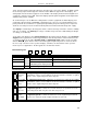
53ML5100 Manual Loading Station ANO0 Tag Name (A244) ANO0 Digital Readout ANO0 Engineering Units ANO0 Output Bar CHANNEL 1 ANO0 Scale Values ANO1 ANO1 ANO1 ANO1 Tag Name (A245) Digital Readout Engineering Units Output Bar Heavy Border Indicates Active Window CHANNEL 2 ANO1 Scale Values 3 Push Button Figure 3-2. Display 1 - Dual Channel Manual Loader (Chs.
Section 3. Displays and Push Buttons ANI0 Tag Name (A224) ANI0 Engineering Span (C256) 50 Segment Vertical Axis Process Variable (ANI0) Process Variable Digital Readout (ANI0) ANI0 Engineering Units (A298) Process Variable Bar (ANI0) CHANNEL 1 ANI0 Zero (C276) 40 Segment Horizontal Axis Output Bar (ANO0) Closed Valve Indicator (ANO0 Reverse Valve [L109]) Open Valve Indicator ANO0 Digital Readout Figure 3-4. Display 3 - Manual Loader with Analog Input (Ch.
53ML5100 Manual Loading Station ANI0 Tag Name (A224) ANI0 Engineering Span (C256) 50 Segment Vertical Axis ANO0 Setpoint (Output Indicator) Setpoint (ANO0) Setpoint Digital Readout (ANO0) ANI0 Engineering Units (A298) Process Variable (ANI0) Process Variable Bar (ANI0) Process Variable Digital Readout (ANI0) ANI0 Zero (C276) CHANNEL 1 Figure 3-6. Display 5 - Analog Input Indicator with Setpoint Display (Ch.
Section 3. Displays and Push Buttons 3.2 FRONT PANEL PUSH BUTTONS The front panel push buttons are repeated here from Section 1 because they are used in the engineering mode display overlay examples to enter a key password, display a datapoint, and alter a datapoint. To the right of the display is the vertical keypad and directly beneath the display is the horizontal keypad.
53ML5100 Manual Loading Station 3.3 ENGINEERING MODE OVERLAYS The engineering mode overlays are used to make the necessary parameter entry selections for the operator displays. The entries are made to addressed datapoints via the overlay single edit line at the bottom of the display. It should be noted that engineering mode has a 20 second timeout if it is accessed and its functions (e.g., configure or display) are not used. 3.3.
Section 3. Displays and Push Buttons CONFIGURE Prompt KEY? Prompt A Key Entered on the Edit Line POINT Query Figure 3-8.
53ML5100 Manual Loading Station 3.3.2 DISPLAYING A DATAPOINT The following procedure illustrates how to display the contents of datapoint B012, which is the display brightness index (the normal setting is 4; 0 is the brightest and 7 is the dimmest setting). Figure 3-9 contains supporting illustrations for the display procedure described in Table 3-2. Table 3-2. Procedure to Display a Datapoint Step 1 2 3 4 Press Once l Shift Result Press to Locate Target Char.
Section 3. Displays and Push Buttons 3.3.3 ALTERING A DATAPOINT The procedure in Table 3-3 illustrates how to alter the contents of datapoint C256, which is ANI0 Engineering Span, from 100 to 50. Figure 310 is provided to show the maximum input character length for the engineering mode edit line. The edit line can accept ten characters. The full ten character field is used primarily for the A type datapoint text strings (tag names).
53ML5100 Manual Loading Station 3.4 FRONT PANEL PUSH BUTTON ALTERNATIVES There are three alternative methods other than the front panel push buttons for accessing and changing database parameters. All three methods to display and/or alter database parameters are listed as follows: 1. Using a personal computer running the Micro-Tools configuration program that is supplied as part of the 53MT6000 software package. 2.
Section 3. Displays and Push Buttons 3-11 Figure 3-11.
53ML5100 Manual Loading Station 3.4.1 USING THE HAND HELD CONFIGURER The Hand Held Configurer (HHC) is a portable terminal designed to interface with the instrument through the configuration port that is located behind the pull-down door on the front panel of the instrument (see Figure 1-2). The HHC is available in two versions: 1. A Standard HHC with capabilities to display or alter specifically addressed parameters in the instrument database. The part number to order this HHC is 698B182U01. 2.
Section 3. Displays and Push Buttons 3.4.1.2 DISPLAYING A DATABASE PARAMETER To DISPLAY a database parameter, press D and enter the parameter ID, then press ENTER. The current value of the parameter is displayed. The parameter ID is the data type identifier (B, L, C, H, F, and A) and point number as described in Table 4-1 of Section 4. For example, to display the value of datapoint B12, press: D B12 . The value presently assigned to B12 is displayed.
53ML5100 Manual Loading Station 3.4.1.4 SETTING OR CHANGING A PASSWORD KEY As a security feature, the instrument can be configured so that a password key is required to access the Engineering Mode configuration function. The password key can only be set by the Hand Held Configurer, the configuration function in the 53HC3300 software package, or the configuration function in the 53WS5000 software package via a PC, and not by the instrument front panel push buttons.
Section 3. Displays and Push Buttons When the HHC-to-controller transfer begins a message is displayed indicating the transfer has started. Another message appears when the transfer is completed. If the transfer fails, an error message is NOT displayed to indicate the transfer failed; the transfer completed message is not displayed after 12 seconds (approximate).
53ML5100 Manual Loading Station 3.4.1.6 SAMPLE HAND HELD CONFIGURER COMMANDS The following table provides a sample of typical Hand Held Configurer Display (D ), Put (P ), and Memory Transfer (T ) commands.
Section 4. Configuration Parameters 4.0 CONFIGURATION PARAMETERS The configuration parameters are used to define the instrument’s personality attributes, so that while still functioning within its designed specifications, it can perform application requirements with greater refinement. Typical configuration parameters are the instrument’s indicator zero point and span, the display tag names, and engineering units of the displayed process value.
53ML5100 Manual Loading Station 4.3 CONFIGURING THE DATABASE MODULES The datapoints in the database modules must be changed to reflect required alterations in the factory standard configuration or when the instrument is re-configured. There are generally two datapoint parameter types contained in the four database modules. The parameter types affect display indications and input-output signals. The four database modules are described in Table 42.
Section 4. Configuration Parameters Table 4-3. Analog Input (ANI) Module Purpose: This module is used to configure the voltage/current input signals (e.g., 0-5 volts [0-20 mA], 1-5 volts [4-20 mA]) and how the input signals are interpreted (linear or square root representation, with or without smoothing ). It is also used to configure the vertical axis range (zero and span) on the display.
53ML5100 Manual Loading Station Table 4-3. Analog Input (ANI) Module Purpose: This module is used to configure the voltage/current input signals (e.g., 0-5 volts [0-20 mA], 1-5 volts [4-20 mA]) and how the input signals are interpreted (linear or square root representation, with or without smoothing ). It is also used to configure the vertical axis range (zero and span) on the display.
Section 4. Configuration Parameters Table 4-4. Analog Output (ANO) Module Purpose: The primary purpose of this module is to select and set the 0 - 20 mA or 4 - 20 mA output signals for ANO0 and ANO1. Title Symbol ANO ANO0 Datapoint Default ANO0 ANO1 ANO0 ANO1 C000 C001 0 0 The value in this datapoint represents the percent of output to be generated by hardware (e.g., 100% output = 20 mA).
53ML5100 Manual Loading Station Table 4-5. Display Module Purpose: This module is used to define the number of displays (six maximum) and to set the display order presentation of the operator displays. The default settings are for six displays in the order shown in Figure 1-1 and listed as follows: 1. Dual Channel Manual Loader (Chs. 1&2), 2. Single Channel Manual Loader (Ch. 1), 3. Manual Loader with Analog Input (Ch. 1), 4. Manual Loader with Analog Input (Ch. 2), 5.
Section 4. Configuration Parameters Table 4-6. System Module Purpose: This module is used to set the instrument tag name and the display brightness. Title Symbol System Module Datapoint Default Display Brightness Index BRIGHT B012 4 Model Number Low (Display Only) A190 Factory Set It contains the first ten characters of the model number. Model Number High (Display Only) A191 Factory Set It contains the last ten characters of the model number.
Section 5. Maintenance 5.0 MAINTENANCE RETAIN THE INSTRUMENT CALIBRATION SHEET The factory set calibration constants for the analog inputs and analog outputs are recorded on the instrument calibration sheet. This sheet should be retained in the event one or more of the constants is inadvertently changed to the wrong value and field recalibration is necessitated. 5.1 SERVICE APPROACH This instrument is a microprocessor based device: data manipulation and sequencing operations are software controlled.
53ML5100 Manual Loading Station Replacing the display unit requires reconnecting the display end of the cable to the new front display panel, inserting the extended portion of the display panel into the instrument cabinet and latching it in place with a screwdriver. After the front display panel is removed, the main printed circuit board can be accessed. The main printed circuit board also has the power supply as well as the microprocessor circuitry.
Section 5. Maintenance 5.3 CALIBRATION The instrument’s analog inputs (ANI0&1) and analog outputs (ANO0&1) normally do not require recalibration. If it becomes necessary to recalibrate the instrument, due to the inadvertent change of the stored calibration values, then this can be accomplished by altering their respective datapoints.
53ML5100 Manual Loading Station 5.6 PARTS LIST The parts list is provided in Table 5-1 and the parts breakdown is illustrated in Figure 5-1. Table 5-1.
Section 5. Maintenance 5-5 Figure 5-1.
53ML5100 Manual Loading Station Figure 5-2.
Appendix A. Database APPENDIX A: DATABASE The database contains five datapoint types. Each datapoint type represents a specific data format: whole integers, alphanumeric text strings, etc. The datapoint types are defined in Table A-1 and the database is listed in alphanumeric order in Table A-2. The gray-tone shading in the Symbol cell of a datapoint indicates the datapoint does not have an assigned symbol. Table A-1.
53ML5100 Manual Loading Station Table A-2.
The Company’s policy is one of continuous product improvement and the right is reserved to modify the information contained herein without notice, or to make engineering refinements that may not be reflected in this bulletin. Micromod Automation assumes no responsibility for errors that may appear in this manual. © 2004 MicroMod Automation, Inc. Printed in USA MicroMod Automation, Inc. 75 Town Centre Drive Rochester, NY USA 14623 Tel. 585-321-9200 Fax 585-321-9291 www.micromodautomation.