
Manual


53ML5100A Manual Loading Station
Supplement to the Instruction Bulletin
Configuration Requirements 5
3.0 CONFIGURATION REQUIREMENTS
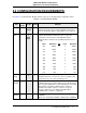
See Table 3-1, Communication Module, Column 3 (Set Up) for the appropriate configuration values.
Table 3-1. Communication Module
Title
Data-
point
Set Up Default Attribute
Address
B01 Select
Address
0
It identifies the address of this instrument on the Datalink
network. Each unit connected to the Datalink network must
have its own unique address. Valid addresses are from 0-31.
Baud
Rate
B02 Select
a
Baud
Rate
253
This datapoint value designates the baud rate of the Datalink
network. The baud rate must be the same for all of the
instruments connected to the same Datalink network.
Datapoint values and their corresponding baud rates are as
follows:
Value Baud Rate OR Value Baud Rate
255 28800
9
28800
254 14400
8
14400
N/A N/A
7
19200
253 9600
6
9600
250 4800
5
4800
244 2400
4
2400
232 1200
3
1200
208 600
2
600
160 300
1
300
N/A N/A
0
110
No
Parity
L256
0 0
This datapoint indicates if parity generation and checking
should be turned on or off. It is set to 0 for even parity serial
byte protocol. It is set to 1 for no parity protocol.
No Byte
Stuffing
L258
0 0
When set to a 1, this datapoint disables the standard MicroMod
communication protocol feature which inserts a 00 (NUL) byte
after every 7E
H
(SOH) that is not the beginning of a message.
(This permits user-written communications software to
determine the number of bytes to expect in a response
message.) It must be set to 0 when using MicroMod
communications software or equipment.
Datalink
Disable
L257
0 0
When set to 0, it permits full Datalink communication
capabilities.
When set to 1, it disables Datalink communication capabilities.