Supplement to Instruction Bulletin Micro-DCI® 53ML5100A 53ML5100 MANUAL LOADING STATION REV. 1 FIRMWARE PN24698 Rev.
MicroMod Automation, Inc. The Company MicroMod Automation is dedicated to improving customer efficiency by providing the most cost-effective, application-specific process solutions available. We are a highly responsive, application-focused company with years of expertise in control systems design and implementation. We are committed to teamwork, high quality manufacturing, advanced technology and unrivaled service and support.
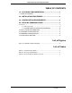
Proportional Speed Floating Controller TABLE OF CONTENTS 1.0 - APPLICABLE DOCUMENTATION........................................ 1 1.1 SCOPE OF CHANGES ................................................................................. 1 2.0 - INSTALLATION PROCEDURES........................................... 3 3.0 - CONFIGURATION REQUIREMENTS ................................... 5 4.0 - DATALINK COMMUNICATIONS........................................... 7 4.1 Protocol .........................................
Proportional Speed Floating Controller 2 Contents
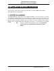
3ML5100A Manual Loading Station Supplement to the Instruction Bulletin 1.0 APPLICABLE DOCUMENTATION ® Instruction Bulletin The information contained in this supplement is applicable to the Micro-DCI 53ML5100A, Manual Loading Station. 1.1 SCOPE OF CHANGES The 53ML5100 Manual Loading Station now has Datalink capabilities as a result of Revision 1 to the firmware EPROM. In a Datalink network, nodes communicate as responders to host personal computer queries.
53ML5100A Manual Loading Station Supplement to the Instruction Bulletin 2 Applicable Documentation
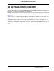
53ML5100A Manual Loading Station Supplement to the Instruction Bulletin 2.0 INSTALLATION PROCEDURES Reference Micro-DCI Instruction Bulletin 53ML900, Upgrading the 53ML5100 Manual Loading Station, for instructions on installing the new EPROM on the main board. Datalink is an interrogator/responder serial interface capable of supporting 32 instruments on a single network. It uses an RS485 physical interface. See the Datalink wiring diagram for this instrument in Figure 2-1.
53ML5100A Manual Loading Station Supplement to the Instruction Bulletin Figure 2-1.
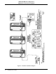
53ML5100A Manual Loading Station Supplement to the Instruction Bulletin 3.0 CONFIGURATION REQUIREMENTS See Table 3-1, Communication Module, Column 3 (Set Up) for the appropriate configuration values. Table 3-1. Communication Module Title Datapoint Address Baud Rate Set Up Default Attribute B01 Select Address 0 It identifies the address of this instrument on the Datalink network. Each unit connected to the Datalink network must have its own unique address. Valid addresses are from 0-31.
53ML5100A Manual Loading Station Supplement to the Instruction Bulletin 6 Configuration Requirements
53ML5100A Manual Loading Station Supplement to the Instruction Bulletin 4.0 DATALINK COMMUNICATIONS Datalink communications capabilities are now provided in the 53ML5100 Manual Loading Station. Datalink Information in this supplement can also be applied to the existing configuration port binary mode as follows: 1. The configuration port data rate is still 9600 baud, with 8 data bits, and no parity. 2.
53ML5100A Manual Loading Station Supplement to the Instruction Bulletin 4.1 Protocol The Datalink protocol requires the host personal computer to initiate all transactions. There are two basic categories for all of the Datalink message types: Interrogate, which is used to read data from an addressed instrument, and Change, which is used to alter a value in an addressed instrument. The addressed instrument decodes the message and provides an appropriate response.
53ML5100A Manual Loading Station Supplement to the Instruction Bulletin 4.1.1 Message Types The types of messages that are sent between the host personal computer and a Datalink network instrument are formatted as follows: HOST PERSONAL COMPUTER TO INSTRUMENT: 1. INTERROGATE - This message requests up to 20H (32 decimal) consecutively stored bytes, beginning at the specified memory address location of the addressed instrument. 01111110 E0H + I.A. NUM LO ADD HI ADD LRC 2.
53ML5100A Manual Loading Station Supplement to the Instruction Bulletin 4.1.2 COMMUNICATION TRANSACTION EXAMPLES Transaction A Example Host personal computer requests 9 bytes of data beginning at hexadecimal memory address 1000H from the instrument which has Datalink address 03. 1. Host personal computer sends INTERROGATE message. 01111110 11100011 00001001 00000000 00010000 11111100 SOH Command + I.A. NUM LO ADD HI ADD LRC 2. Instrument sends RESPONSE message.
53ML5100A Manual Loading Station Supplement to the Instruction Bulletin 4.2 CALCULATING DATA ADDRESSES If communications software must be generated to accommodate unique Datalink applications requirements, then the instrument memory address scheme must be known for proper data bit (e.g., L datapoints) and data byte (e.g., B, C, H, and A datapoints) memory location determination. ✎ Note Hexadecimal (base 16) numbers used in this section are identified with a subscript H after the number.
53ML5100A Manual Loading Station Supplement to the Instruction Bulletin Table 4-2. Controller Memory Address Scheme (Continued) Data Type Base Memory Address Byte Size H F00H 5 A (F)* 1400H Data Format Address = H Base + (5 X H Number) Represents high precision floating point = F00H + (5 X H Number) values that have a resolution of one part in Address example: H001 location 2 billion (31 bits) and a dynamic range of F00H + (5 X 1) = F00H + 5D = F00H ± 1038.
53ML5100A Manual Loading Station Supplement to the Instruction Bulletin 4.3 SOFTWARE CHARACTERISTICS 1. Transparency Rule - whenever 7E hexaecimal is transmitted as anything other than SOH, a 00 byte will be inserted directly following it (byte stuffing). 2. All transactions are initiated by the host personal computer. 3. All instruments begin their response within 10 ms after the end of the transmission by the host personal computer; otherwise, a faulty transmission may be assumed. 4.
53ML5100A Manual Loading Station Supplement to the Instruction Bulletin 14 Datalink Communications
The Company’s policy is one of continuous product improvement and the right is reserved to modify the information contained herein without notice, or to make engineering refinements that may not be reflected in this bulletin. Micromod Automation assumes no responsibility for errors that may appear in this manual. © 2005 MicroMod Automation, Inc. MicroMod Automation, Inc. 75 Town Centre Drive Rochester, NY USA 14623 Tel. 585-321-9200 Fax 585-321-9291 www.micromodautomation.