
User guide

Training Manual
Advanced Configuration Lab
6 - 4
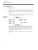
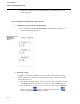
2. Assign database locations to the controller math block
• We will assign database locations C090 and C091 to the math block inputs,
database location B123 and B124 (math block’s A & B inputs). When using FCS
for control purposes any “C” type data in the range 0-255 can be assigned to the
math block inputs including those “C” type data assigned to analog inputs and
outputs.
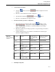
• Select location B123 using the
/ buttons to select the digit and then use the
/
buttons to modify the value of the digit. The point entry should look like
POINT
L
B123. Press the F3 to accept the entry.
• The screen should now display the current contents of B123, B123
L
21.
Enter a value of 90 (for database location C090), B123
L
90 and then press
F3 to enter.
• Similarly select location B124 and enter a value of 91 (for database location
C091).
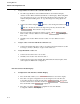
3. Assign a value of 2 for the math block’s function code.
• Select location B126 and enter a value of 2 for that location. The function we will
be using is: (A*K1) + (B*K2). C is ignored and will be zero.
4. Assign K1 and K2 a value of 1.
• Select location C76 and enter 1 as its value
• Similarly select location C77 and enter value 1.
• Select location C78 and enter value 0. This will disable the unused input C. This
will complete the Math block configuration.
Part B: Parameter Module Display:
1. Configuration of the Parameter Module Display:
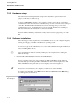
• Press the F1 button until you see CONFIGURE 5at the bottom of the display.
• Press F3 to accept the configuration mode. On design level A controllers, the
bottom line should now display the following: POINT
L
. On a design
level B controller, the bottom line should read DATAPOINT 5 or MODULE .
Press the F2 button until MODULE is displayed.
• Press F3 to accept the MODULE configuration mode. The Module
Configuration Menu is now displayed.