
User guide


Training Manual
Front Face Configuration Lab – Datapoint Configuration
4-6
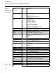
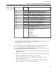
Table 4- 2 Cont.
Alarm configuration
in Single Loop
Controller
Memory
Location
Value Parameter
C103 Process Limit 1
C104 Process Limit 2
C105 Alarm Deadband
B335
0
1
2
3
4
5
6
Selection of Alarm Function
Hi/Low Alarms; C103 = High, C104 = Low
No Alarms
Hi Only; C103 = High
Low Only; C104 = Low
Hi/Hi-Hi; C103 = High, C104 = Hi-Hi
Low/Low-Low; C103 = Low, C104 = Low-Low
Deviation from Setpoint; C103 = positive
Deviation, C104 = negative Deviation
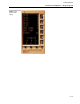
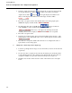
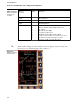
# Alarm “Ticks” will appear on the standard control loop display. They are added to the
left of the process variable bargraph, refer to figure 4.2.
Figure 4-2.
Single loop display
with alarm ticks