
User guide

Training Manual
F-TRAN Programming Lab
10- 16
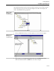
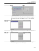
• Try different values for C0 and make sure H0 changes to that value.
10.4.2 Part II – A more advanced F-TRAN Program
The Part I was intended to demonstrate the procedure for creating, compiling, building,
downloading and running an F-TRAN program. This demonstration is hardly adequate to
perform any real functions. This part of the lab is intended to add some more of the
mechanics of F-TRAN programming.
We will program a simple PID control function and some associated functions. We will
also use some of the pre-existing subroutines in our program. In this program we will
perform the PID with Remote setpoint. We will also set Reset Feedback Equal to Last
Output and set Reset Tracking Based on Auto-Manual Selection of the control loop.
1. Create a new F-TRAN program:
• Follow the steps explained in Part I of this manual and create a new F-TRAN
program. Give it a name Ftran2.
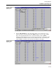
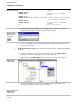
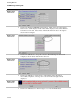
• Enter the program instructions given in the next figure in the F-TRAN editor.
Figure 10.26.
Control F-TRAN
Program
\ ***** This is a header *****\
#define ANI0 H000
#define ANI1 H001
#define ANO0 C000
#define PV C100
#define OUT C102
#define RSP C120
#define RF C127
#define AUT L107
#define CTC L123
#define SPGEN G000
#define DVGEN G004
#define PID G008
#define AMSW G012
#define DISPLAYS G022
PV = ANI0 \ Read Process Variable From ANI0 \
RSP = ANI1 \ Read Remote Setpoint From ANI1 \
RF = OUT \ Set Reset Feedback Equal to Last
Output \
CTC = AUT \ Set Reset Tracking Based on Auto-
Manual Selection \
SPGEN \ Setpoint Generator Subroutine \