53MC5000 Instrument Engineer Course No.
The Company MicroMod Automation is dedicated to improving customer efficiency by providing the most ost-effective, application-specific process solutions available. We are a highly responsive, application-focused company with years of expertise in control systems design and implementation. We offer customers application expertise, service and support worldwide. We are committed to teamwork, high quality manufacturing, advanced technology and unrivaled service and support.
Preface About this book This training manual is for beginners who are new to the Micro-DCI product line and in particular, the 53MC5000 Process Control Station (controller). This book is a jumpstart guide and provides the essentials for understanding the 53MC5000 controller. The tutorials and labs provided in this book explain the hardware, programming methods, and operation of the 53MC5000 controller.
Table of Contents Chapter 1: Introduction to the 53MC5000 Process Control Station. Chapter 2: Hardware Familiarization Lab – Explains how to take controller apart to look at the different hardware parts. Chapter 3: Front-face Configuration using FCS. Explains how to load simple control strategies from the front of the instrument using the keys. Chapter 4: This is an extension of the front face configuration. Explains how to override the settings of the loaded single loop control strategy.
1 Introduction 1.1 The Micro-DCI product line: The current Micro-DCI product line includes the following: • 53MC5000 Process Control Station • Optional I/O Modules • Optional Communication modules • Micro-Tools Software • Micro-DCI Communication Services Software 1.1.1 53MC5000 Process Control Station: This is a multi-loop controller and is the foundation of the MicroDCI product line. It can perform many process control functions from simple PID to complex control strategies.
Training Manual Introduction 1.2 Configuration/Programming Methods: The 53MC5000 Process Control Station can be programmed in 3 different ways: 1.2.1 FCS –Flexible Control Strategies: FCS is a library of math, logic and process control function blocks or modules that can be soft-wired together to form complete control strategies.
Training Manual Introduction 1.2.2 FCIM: Flexible Control Interconnection Modules This method uses pre-defined control modules such as Math, Logic, Control and Input/Output modules in a user-defined sequence of steps to configure the control strategy. The user does not need any knowledge of computer programming. FCIM can be configured from: • Controller front face using the faceplate buttons • MicroTools Application Software 1.2.
Training Manual Introduction 1.3 Communication Options The 53MC5000 can be accessed using several different communication methods. There are two standard communication ports provided; the Front Configuration Port and the DataLink communications port. MicroLink, an optional third communication port, can also be added. Configuration Port: On the faceplate of the controller, an RS232 communication port is provided. This is commonly used to make a point-to-point connection between a PC and the controller.
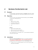
2 2.1 Hardware Familiarization Lab Foreword It is important that you understand the hardware of 53MC5000 controller. The controller is made up of different parts. Some of these parts are mandatory and some are optional. 2.2 Objectives In this lab we will open the instrument and study its hardware parts.
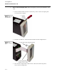
Training Manual Hardware Familiarization Lab 2. Remove the Front Display Panel: After removing the power, keep the instrument on the table. • Insert a small screwdriver into the notch at the top center of the front display panel as shown in the next figure: • Twist the screwdriver to release the latch and slide the bezel straightforward. • Disconnect the display ribbon cable from its socket at the back of the panel to remove the front display unit. Figure 2 .
Training Manual Hardware Familiarization Lab 3. Remove the expansion chassis (if present): • Use the metal option card retainer to free the expansion board from its socket. Grab the retainer and pull forward to free the expansion chassis from its backplane edge connector. • Carefully slide the expansion board forward to access the ribbon cable • Disconnect the ribbon cable from J11 on the expansion board • Continue to slide the expansion board from the instrument. Figure 2 .2.
Training Manual Hardware Familiarization Lab Figure 2 .3. MC5000 – Expansion board 4. Remove the Main board from the housing: • Figure 2 .4. MC5000 – Removing the main board 2-4 Use the plastic front edge board ejector to remove the main printed circuit board (PCB) from its rear terminal board socket and carefully slide the board forward. See figure below: Use your finger to pull back on the top of the ejector. This will leverage the board from its rear edge connector.
Training Manual Hardware Familiarization Lab • The main PCB consists of the CPU, RAM, PROM etc. and is shown with the power supply board attached. Figure 2.6 shows a design level A main PCB while figure 2.7 shows a design level B main PCB. Figure 2 .5. MC5000A – Main board parts Figure 2 .6.
Training Manual Hardware Familiarization Lab 5. Rear Terminations: • Figure 2 .7. MC5000 – Terminations 2-6 Look at the back of the instrument. The rear termination is a two-piece design, with a right and left half. The right terminal board is the standard rear terminals and accepts the main PCB. This terminal board includes connections for the power supply AC or DC power, the standard analog and discrete I/O and the DataLink communications for the instrument.
Training Manual Hardware Familiarization Lab Figure 2 .8.
Training Manual Hardware Familiarization Lab 5. Interface Terminal Boards (ITB): • Figure 2 .9. MC5000 – Interface Terminal Boards 2-8 Standard Inputs and Outputs can be terminated on the rear terminal blocks of the controller. When Optional I/O are added to the controller, there is insufficient space to provide terminal for every combination of I/O and communication option. Instead, terminal blocks for the optional I/O are remotely mounted from the controller.
Training Manual Hardware Familiarization Lab 2-9
Training Manual Hardware Familiarization Lab Notes: 2 - 10
3 3.1 Front Face Configuration – Single Loop Lab Foreword This lab is designed to help you learn the basics of front face configuration, as well as demonstrate the simple steps to configure a simple single Loop PID. Physical Addressed Referenced Device: The 53MC5000 Process Control Station is an Address Referenced device. This means that all data for functions, inputs, outputs, etc. are referenced by pre-assigned memory locations.
Training Manual Front Face Configuration – Single Loop Lab 3.3 Instructions 3.3.1 Defaulting the controller 1. Enter configuration mode: • Press the E-mode button (also referred to as the DOT button – the first button from the right). This button is used for acknowledging alarms as well as for entering the engineering mode. If there are active alarms in the display, you may have to press the button more than once to enter the engineering mode.
Training Manual Front Face Configuration – Single Loop Lab Figure 3 .2. MC 5000 display and buttons 2. Select the data point B0 to default the controller (to return the instrument’s configuration to factory default settings): • Be certain that the “cursor” L is in the right most character position by pressing the output increase pushbutton. • Press the setpoint-increase right corner of the display. • Move the letter B to the left by pressing the output decrease pushbutton once.
Training Manual Front Face Configuration – Single Loop Lab Figure 3 .3. Loop display and instrument in CONFIGURE mode 3. • Press the ENTER (F3 – third key from the left) key to accept the selection. Now we have selected the database location B0. • After you pressed the F3 key, the bottom line of the display should look like: B0 1 The value of B00 will be displayed in the lower right L corner of the display. Change the value of B0 to 98. • Press the setpoint-increase pushbutton.
Training Manual Front Face Configuration – Single Loop Lab Figure 3 .4. Instrument defaulted – MicroDCI Logo # The database location B0 is very special and is referred to as the Function Index or FIX of the controller. The Function Index represents the control program or strategy that is currently executing. The value stored in B0 can differ from controller to controller. Some of the values of B0 and the corresponding controller state are as shown below: Table 3 .
Training Manual Front Face Configuration – Single Loop Lab 4. Defaulting the Flexible Control Strategy Wirelist: • Use setpoint and output pushbutton to select database location B16. The bottom line of the display should look like: POINT LB16 then ENTER the selection by pressing F3. • Database location 16 will always have a value of 0 when displayed. Once a new strategy is loaded using B16, the value is automatically returned to 0.
Training Manual Front Face Configuration – Single Loop Lab 7. Exiting the Engineering mode: • Do this by pressing the DOT pushbutton. The engineering mode line at the bottom of the display will be removed and the screen information returned to normal. The instrument will display the loop display as shown in the next figure: Figure 3 .5. Single loop display 8. Single Loop PID Display: • The above single-loop controller display is for displaying PV, SP and OP in numeric and bar formats.
Training Manual Front Face Configuration – Single Loop Lab 9. View the other displays: • Press and hold the F2 button. The display GRID will appear as shown in the next figure. There are 5 boxes (displays) in the GRID. • Release and press F2 again. The Single loop with PV trending should appear next as shown in the next figure. This display shows PV, SP and OP in numeric format. It also displays the PV as a graphical trend. Figure 3 .6.
Training Manual Front Face Configuration – Single Loop Lab Figure 3 .7. PV Trend display • Press F2 again. The Con 0 Tuning Parameter display appears. This display shows Proportional Band, Reset Time and Derivative Time. You can use the / buttons to select the parameter and then press the Enter key (F3 button). The selected parameter database address and the value will be displayed at the bottom. You can now use the / and / buttons now to change the value of the selected parameter.
Training Manual Front Face Configuration – Single Loop Lab Figure 3 .8. Tuning display • 3 - 10 Press F2 again to display the CON-0 ALRM display. This display shows the Process limits 1 and 2 for the process alarm and also the Alarm band.
Training Manual Front Face Configuration – Single Loop Lab Figure 3 .9. CON-0 Alarm Parameter Display # Remember to press the F3 button after changing values. • Press F2 again.
Training Manual Front Face Configuration – Single Loop Lab Figure 3 .10. System Status Display • 3 - 12 This display shows system parameters like the Function Index (FIX), Control Program scan rate (SCAN), the Instrument Address (IA), etc. There are 2 pages in this display. Press and hold the F3 button to view the next page. The second page shows additional parameters including the option card status and the controller run time counter.
Training Manual Front Face Configuration – Single Loop Lab Figure 3 .11.
Training Manual Front Face Configuration – Single Loop Lab Notes: 3 - 14
4 4.1 Front Face Configuration Lab – Datapoint Configuration Foreword In the previous lab, we learned to default the instrument, load and run a single loop Flexible Control Strategy. The single loop control strategy we loaded had all the database or control parameters in their default values and ranges. It is important to change some of these default values to suit the process application. 4.
Training Manual Front Face Configuration Lab – Datapoint Configuration • Using the output decrease button , shift the letter C one space left. Using the UP arrow again, display the number 2 and then shift it to the left by pressing the output decrease button . Using the button again, display the number 5 and shift it to left. Display the number 6 next. The display should look like: POINT LC256 • Press F3 to accept the selection. The default value for the analog input span is 100.00.
Training Manual Front Face Configuration Lab – Datapoint Configuration Figure 4-1. Configuration Mode # Refer to Table 4-1 for a complete listing of commonly used memory locations in the single loop control strategy. Remember to press F3 after selecting the location and also after changing the location.
Training Manual Front Face Configuration Lab – Datapoint Configuration Table 4-1 Commonly Used Locations in Single Loop Controller Memory Location Value Parameter 1 0 99 Function Index Flexible Control Suspended, All outputs frozen Default database B000 B016 1 2 3 4 5 98 C256 ANI0 Span (engineering span) C276 ANI0 Zero (engineering zero) B269 Digital Filter (smoothing the constant) L440 1 0 ANI1 Span (RSP, engineering span) C277 ANI1 Zero (RSP, engineering zero) B270 Digital Filter (smoot
Training Manual Front Face Configuration Lab – Datapoint Configuration Commonly Used Locations in Single Loop Controller Location C108 Rate time (tuning parameter in minutes) C111 Manual Reset (tuning parameter in percent C115 Control Range (Control Functions) C116 Control Lower Range (Control Functions) C125 Setpoint Limit high (Control Functions) C126 Setpoint Limit Low (Control Functions) L106 Control Action (Control Functions) L109 Reverse Value (Control Functions) L114 Auto Enable (
Training Manual Front Face Configuration Lab – Datapoint Configuration Table 4- 2 Cont. Alarm configuration in Single Loop Controller Memory Location Value C103 Process Limit 1 C104 Process Limit 2 C105 Alarm Deadband B335 0 1 2 3 4 5 6 # Figure 4-2.
Training Manual Front Face Configuration Lab – Datapoint Configuration 5. Testing the alarm limits • The controller should currently be in the manual mode. There are two ways to generate an alarm with the training equipment we are using. The analog output of the controller will have a loop-back connector wired to the analog input. • If the current output is zero, the controller should already be in alarm. • Press the Dot button once to acknowledge the flashing alarm.
Training Manual Front Face Configuration Lab – Datapoint Configuration Notes: 4-8
5 5.1 Front Face Configuration Lab Part 3 – Module Configuration Foreword In Part 2 of the Front Face Configuration lab, we learned to modify part of the controller’s database to suit or process application. In that lab we access the specific database locations associated with the analog inputs span and zero, the control loop’s range, the control loop’s setpoint limits, etc. To accomplish these changes it was necessary to know the database locations these values are stored in.
Training Manual Front Face Configuration Lab Part 3 – Module Configuration • Press F3 to accept the MODULE menu will be displayed: configuration mode. The following Figure 5.1 Configuration main menu display 2. Change the Analog Input’s Span and Zero: • We will change Analog Input 0’s value of Span to 300.00 and Zero to 0. • There will be a pointer along the left side of the menu.
Training Manual Front Face Configuration Lab Part 3 – Module Configuration • Press F3 to accept the selection. The controller will display a list of the analog input module ID numbers. If tag names for the analog inputs have been previously assigned, the tag names will be displayed along side the module ID numbers. • Using the setpoint increase or decrease 0- menu item and press the F3 button. • Analog Input Module 0 parameters will be displayed on the screen as shown below: Figure 5.
Training Manual Front Face Configuration Lab Part 3 – Module Configuration Figure 5.3 Analog Input Parameter configuration main menu display • Using the press F3. • The display screen now shows the SPAN parameter • The SPAN is changed by using the and pushbutons, move the pointer to the SPAN parameter and Figure 5.4 Analog Input Parameter configuration main menu display the / 5-4 / / buttons to select the digit and then use to modify the value of the digit. Change the value to 300.
Training Manual Front Face Configuration Lab Part 3 – Module Configuration 3. • Press F3 to accept this value. The display is returned to the Analog Input parameter list. The new SPAN value is displayed. • Using the and pushbutons, move the pointer to the ZERO parameter and press F3. The default value of Zero is 0. • Press F3 now to accept this default value. We have now configured the value of Span and Zero for the analog input. Change the control range for the single loop.
Training Manual Front Face Configuration Lab Part 3 – Module Configuration Figure 5.6 Control Module Parameter Groupings list Figure 5.7 Control Module General configuration menu display 5-6 • The control module configuration is broken into logical groupings of configuration parameters. • Using the press F3. • The display screen now shows the parameters associated with the General configuration category.
Training Manual Front Face Configuration Lab Part 3 – Module Configuration • Using the F3. • The display screen now shows the IR parameter • The IR is changed by using the and pushbutons, move the pointer to the IR parameter and press Figure 5.8 Control Module Instrument Range configuration display / / buttons to select the digit and then use the / to modify the value of the digit. Change the value to 300. • Press F3 to accept this value.
Training Manual Front Face Configuration Lab Part 3 – Module Configuration 4. Change the Tag Name for the Control Module 0. • Changing the Control module tag name by first selecting TAG from Control Module General configuration list using the / keys. • Press the F3 button to select the TAG configuration. The TAG configuration screen should appear as in the figure below. • Tag names are created from alpha-numeric characters.
Training Manual Front Face Configuration Lab Part 3 – Module Configuration • Press the F2 button and notice that the highlighted symbol changes as the cursor position changes. When you reach the end of the tagname, the cursor wraps back to the first position. • Press the F2 button until the cursor is in the first character position. Using the / buttons to select the character within a row of symbols and use the / to select the row of characters.
Training Manual Front Face Configuration Lab Part 3 – Module Configuration you have 5 seconds to press the DOT button again to return back to your last place in the engineering mode. • 5 - 10 Press the DOT button to exist engineering mode. Wait 3 seconds and press the DOT button again. You should return to the last place before you exited. Configuration changes that are made using the Menu mode like the Datapoint mode are immediate.
6 Advanced Configuration Lab 6.1 Foreword Many control strategies involve calculations and math functions besides PID control. The 53MC5000 controller can perform math and logic functions in addition to PID control. Table 5.1 lists the function blocks that are available in the 53MC5000 controller. 6.2 Objectives In this lab we will add 2 inputs and show the result in a display. We will also configure a display for this purpose.
Training Manual Advanced Configuration Lab 6.3 Instructions Part A: Math Function Block: The Math function block (or module) allows the user to select a math function and attach input values that will use the selected function. The inputs for the math function will be assigned specific database locations. The output of the block can be accessed from another math function. Each math block has 3 inputs and a Function Code to select a specific math function.
Training Manual Advanced Configuration Lab Table 6.1. Function Code Math Function 0 A 1 (K1*A)+K2 2 (K1*A)+(K2*B)+(K3*C) 3 (K1*A*B*C)+K2 4 (K1*(A/B))+(K2*C) 5 ((K1*A)+(K2*B)/C)+K3 6 ((K1*A*B)/C)+K2 7 ((A+K1)/B+K2))*K3 8 (K1*ABS(A))+K2 9 K1*(A*A((K2*B)+K3)) 10 K1*(2*2((K2*A)+K3)) 11 K1*LOG((K2*A)+K3) 20 Limiter (K1
Training Manual Advanced Configuration Lab 2. Assign database locations to the controller math block • We will assign database locations C090 and C091 to the math block inputs, database location B123 and B124 (math block’s A & B inputs). When using FCS for control purposes any “C” type data in the range 0-255 can be assigned to the math block inputs including those “C” type data assigned to analog inputs and outputs.
Training Manual Advanced Configuration Lab 2. 3. Table 6.2. Select Parameter Module 0 • Using the menu list. • Press F3 to enter the Parameter module configuration. • Select Parameter Module 0, 0-CON-0 TUNE using the • Press F3 to enter Parameter 0 configuration menu. / buttons, select the PARAMETER Module configuration from the buttons. Parameter Module 0 parameter configuration • Select and modify the module tag name.
Training Manual Advanced Configuration Lab • When all the changes have been entered, simply press the DOT button to exit engineering mode. Part C: Displaying the Modified Parameter Module: 1. Configuration of the Parameter Module Display: • Press the F2 button until the MATH DEMO parameter module is displayed. It should look like the figure below. Figure 6.2. MATH DEMO Display 2. Testing the results Remember we tied Input 0 and Input 1 of the controller as the inputs for the math function.
Training Manual Advanced Configuration Lab • Press the F3 key to accept the value. INPUT 0’s value should now indicate 100.0. The result of the math module sum should also be displayed as the RESULT. • Use the • Repeat the procedure above to change the value of INPUT 1 to 100.0. The sum should now be 200 in the RESULT parameter value. / buttons to select INPUT 1 on the Parameter module display.
Training Manual Advanced Configuration Lab Notes: 6-8
7 7.1 Introduction to Micro-Tools Foreword Micro-Tools is a Windows XP Professional based Configuration Software for the MC5000 family of Process Control Stations. Micro-Tools helps reduce controller configuration and maintenance time by providing an easy to use view into the database and configuration of the instrument. 7.2 Objectives In this lab we will install Micro-Tools and Micro-DCI Comm Services in the computer.
Training Manual Introduction to Micro-Tools 7.2.2 Hardware setup: We will need the following hardware setup for this lab. This is optional, but for the purpose of this lab, we will set it up. Connect a 53MC5000 Controller to the computer’s serial port. Do this by connecting a communication cable from the front communication port of the controller to the serial port of the PC. The MicroDCI Communications Services will support up to four serial communications ports.
Training Manual Introduction to Micro-Tools 2. Type D:\SETUP.EXE or E:\SETUP.EXE etc., (depending on the drive letter assigned for use with your CD-ROM drive) and click on OK or press ENTER. Micro-DCI Master Setup will have a master menu from where you can install various Micro-DCI applications like: • Micro-PWC • Micro-DCI Comm Services • Loop Master • Micro-Tools Also included on the CD are several “Quick Tours” of the Micro-PWC and the 53MC5000 products.
Training Manual Introduction to Micro-Tools 4. Click on Micro-Tools Setup button in this menu. The Micro-Tools Setup will start as shown below: Figure 7.3. Micro-Tools Setup 5. Click on the Next button to proceed. The Setup will start and display the License Agreement screen as shown in the next figure.
Training Manual Introduction to Micro-Tools Figure 7.4. Micro-Tools Setup License Agreement 6. Click on the “I accept the terms… selection and then click Next to proceed with the installation Figure 7.5. Micro-Tools Setup Customer Information 7. The Customer Information screen will be displayed. If this screen does not automatically fill in, enter a User Name and Organization into the respective areas of this screen. When the entries have been made, click Next to proceed with the installation.
Training Manual Introduction to Micro-Tools Figure 7.6. Micro-Tools Setup Setup Type 8. The Setup Type screen will be displayed next. This allows the installer to select the complete installation (recommended) or a custom installation. Custom installations require a previous knowledge of the software to be installed. Figure 7.7.
Training Manual Introduction to Micro-Tools 9. Once the preliminary information has been entered, the MicroTools software is Ready to Install. Click Install when you are ready to proceed. Figure 7.8. Micro-Tools Setup Installing Micro-DCI Micro-Tools 10. When installing the MicroTools software for the first time, MicroTools will require the installation of the Micro-DCI Communications Services.
Training Manual Introduction to Micro-Tools Figure 7.10. Micro-Tools Setup Communication Services InstallShield Wizard 11. When the InstallShield Wizard is ready, click Next to proceed with the Micro-DCI Communication Services installation. Figure 7.11. Micro-Tools Setup License Agreement 12.
Training Manual Introduction to Micro-Tools Figure 7.12. Micro-Tools Setup Communication Services Customer Information 13. Once again the Customer Information screen will be displayed. If this screen does not automatically fill in, enter a User Name and Organization into the respective areas of this screen. When the entries have been made, click Next to proceed with the installation. Figure 7.13.
Training Manual Introduction to Micro-Tools 14. The Setup Type screen will be displayed next. This allows the installer to select the complete installation (recommended) or a custom installation. Custom installations require a previous knowledge of the software to be installed. Figure 7.14. Micro-Tools Setup Communication Services Ready to Install 15. Once the preliminary information has been entered, the Communications Services software is Ready to Install. Click Install when you are ready to proceed.
Training Manual Introduction to Micro-Tools Figure 7.15. Micro-Tools Setup Communication Services Server Name 16. As the setup window indicates, you must enter a “Server Name” in place of the three question marks. DO NOT PROCEED using the three question marks as the server name. You may select any name even if temporary. The name can be changed following the installation completion. Figure 7.16. Micro-Tools Setup Communication Services Server Name 17. udci00 is an example of a Server Name.
Training Manual Introduction to Micro-Tools Figure 7.17. Micro-Tools Setup Communication Services Software Installation 18. The installation will proceed automatically. Figure 7.18. Micro-Tools Setup Communication Define A New Network 19. Our class will only require one communication network. Click No to continue with the installation.
Training Manual Introduction to Micro-Tools Figure 7.19. SUPER32 Setup Network Wizard 20. The Network Wizard allows you to select one of three kinds of communication port. For the purposes of this class, select COM: PC Serial Port from the list and then click Next. Figure 7.20. SUPER32 Setup Network Wizard Network Attributes 21. Each serial communication port is required to have a name. This name is referred to as a Network Name. Each Network Name should be unique. The names COM1, COM2, etc.
Training Manual Introduction to Micro-Tools 23. When your selection and entries have been made, click Next to continue. Figure 7.21. SUPER32 Setup Network Wizard Network Mode 24. There are three modes that each port can be configured for. The Master and Backup mode are for communication networks that will participate in a Master/Backup configuration.
Training Manual Introduction to Micro-Tools Figure 7.22. SUPER32 Setup Network Wizard Communication Settings 26. Each communication port can have unique Communication Settings. These settings are the communications Baud Rate, Parity and the number of Databits per character. The 53MC5000 has several different communications ports. The two standard communication ports are the Configuration Port on the front of the controllers and the MicroDCI DataLink communications on the rear of the controller.
Training Manual Introduction to Micro-Tools Figure 7.24. SUPER32 Setup Network Wizard Complete 29. The new network will be added to the Communication Services. If the addition is successful, a message to that affect will be displayed. Click OK to acknowledge the message. Figure 7.25. SUPER32 Setup Communication Services Add Another Network 30. You will be asked if you would like to add another network. For the purposes of this class we only need a single network.
Training Manual Introduction to Micro-Tools Figure 7.27. SUPER32 Setup Communication Services Notepad 32. Once you have read the file, you can proceed with the installation by closing the READ ME file. Figure 7.28. Micro-Tools Setup Communication Services Software Installation Complete 33. Click Finish to acknowledge the completion of the Communication Services installation.
Training Manual Introduction to Micro-Tools Figure 7.29. Micro-Tools Setup Resumes 34. Following a short pause, the MicroTools software installation will resume automatically. Figure 7.30. Micro-Tools Setup Software License Manager 35. After the MicroTools software has been copied, the Micro-DCI software License Manager is opened. The MicroTools software is licensed and protected using a hardware/software protection scheme.
Training Manual Introduction to Micro-Tools 36. Click the Add License icon Administrator Tool bar or select Add New License from the MicroDCI License Figure 7.31. Micro-Tools Setup Software License Administrator 37. If the hardware sentinel key is installed in the appropriate port, the License Administrator will attempt to read the hardware key. If successful, the hardware key ID number will automatically be entered in the Host ID box of the license window. 38.
Training Manual Introduction to Micro-Tools spaces (even thought the license paperwork uses spaces after every fourth character. The spaces are to help make the license string more legible. Figure 7.32. Micro-Tools Setup Software License Administrator Example License 41. Example of a license for Feature udci Version 4.0. The hardware security key ID number is 22178. 42. When the data is entered, click on Save.
Training Manual Introduction to Micro-Tools Figure 7.33. Micro-Tools Setup Software License Administrator License Entry Error 43. If there is an error in the information entered for the license, an error message will be displayed. Click OK to acknowledge the error. Verify and correct the license information and click Save again. Repeat this process until the license is entered correctly. Figure 7.34. Micro-Tools Setup Software License Administrator Example License 44.
Training Manual Introduction to Micro-Tools Figure 7.35. Micro-Tools Setup Software License Administrator Example License 45. When both the Licensed Features have been successfully entered, close the License Administrator window to proceed with the installation. You may close the window using the Tool bar File > Exit or by clicking on the right upper most window X. Figure 7.36.
Training Manual Introduction to Micro-Tools 46. When the installation resumes, an Information window will open. Click OK to acknowledge the window. This Information window will open a READ Me file using Windows NOTEPAD. The READ ME file has information related to the software release. Figure 7.37. Micro-Tools Setup READ ME file 47. Once you have read the file, you can proceed with the installation by closing the READ ME file.
Training Manual Introduction to Micro-Tools Figure 7.38. Micro-Tools Setup Installation Complete 48. The MicroTools installation is complete. Click Finish to acknowledge the completion of the Installation.
7.2.4 Adding Communication Networks: Once MicroTools and MicroDCI Communication Services are installed on your PC, you can add or remove communication networks. These communication networks are used to communicate with one or more controllers. Communication networks are configured using an application within the MicroDCI Communication Services. This application is referred to as SUPER32.
Training Manual Introduction to Micro-Tools Figure 7.40. Micro-Tools Setup Adding a Communication Network 4. Select “Add a new network” from the list. This will start the Network Wizard. Figure 7.41. SUPER32 Setup Network Wizard 5. The Network Wizard allows you to select one of three kinds of communication port. For the purposes of this class, select COM: PC Serial Port from the list and then click Next.
Training Manual Introduction to Micro-Tools Figure 7.42. SUPER32 Setup Network Wizard Network Attributes 6. Each serial communication port is required to have a name. This name is referred to as a Network Name. Each Network Name should be unique. The names COM1, COM2, etc. are reserved and should not be used. 7. The network position is selected from a list of available communication ports. The MicroDCI communication services will compile the list from all the serial ports available within the PC.
Training Manual Introduction to Micro-Tools 9. There are three modes that each port can be configured for. The Master and Backup mode are for communication networks that will participate in a Master/Backup configuration. When configured as a Master/Backup, if the Master communications network should fail, the Backup network assumes the Master role and provides the communication to the controllers. The Backup Network would be a separate communications port in a second PC.
Training Manual Introduction to Micro-Tools Figure 7.45. SUPER32 Setup Network Wizard Finish 13. Review the settings and selection you have made for the serial communications port. If you are satisfied with the selections and settings click Finish to accept these changes. Figure 7.46. SUPER32 Setup Network Wizard Complete 14. The new network will be added to the Communication Services. If the addition is successful, a message to that affect will be displayed. Click OK to acknowledge the message.
Training Manual Introduction to Micro-Tools 15. Once the network has been successfully added, you may expand the tree by clicking on the + in front of each level of the tree. When the serial port network is expanded, any controller(s) connected to the tree will be displayed as a icon.
8 8.1 Micro-Tools Lab Foreword Micro-Tools provides a graphics based interface for the FCS configuration. Micro-Tools uses the MicroDCI Communication Services networks as an interface to the 53MC5000 controllers. The support communications networks that Micro-DCI Communication services supports include the 53MC5000 front serial port, the Micro-DCI RS422/485 DataLink port and the Micro-DCI Micro-Link port(s).
Training Manual Micro-Tools Lab 8.3 Instructions 1. Establishing Online Communications: Lets begin by verifying that we have established communications to one or more instruments. First, we will run the Super32 application to check our networks and identify any controllers that are linked to those networks. Our lab setup should have one network and one controller connected to that network. If the controller is present on the network, then we have communications with the controller.
Training Manual Micro-Tools Lab Figure 8.2. Super32 Tree View Figure 8.3. Super32 Tree View • Assuming that the Controller is connected to the computer and the communications port settings as configured for 9600 baud, 8 Databits, No Parity, you should be able to see SERIAL1 network (or other networks) and the Controller attached to the network as shown in the next figure.
Training Manual Micro-Tools Lab (refer to the MicroTools Installation Lab for additional details on the addition or removal on communication networks). Figure 8.4. Super32 Controller 2. • The Controller’s name (53MC5000 is the default name for the Design Level B 53MC5000 controller) has been read from the controller by Super32. This name is stored as part of the controller’s database. • Click on the “+” by the controller name to view the other tags configured within the controller.
Training Manual Micro-Tools Lab Figure 8.5. Micro-Tools in Start Menu • The Micro-Tools application will launch as shown in the next figure. When starting MicroTools from the Windows Program Manager, MicroTools will always open with the Project Manager as the active window. Figure 8.6. Micro-Tools Administrator Project Manager 3. The Project Manager consists of a tree of folders. When Micro-Tools software is initially installed, several folders will be created automatically.
Training Manual Micro-Tools Lab # A project is a way of organizing all the software resources needed to control an entire process or a process area. Within each project folder, individual controller folders will be created which will contain database files for the respective controller, as well as the FCS or F-CIM configuration and/or any F-TRAN programs for the controller.
Training Manual Micro-Tools Lab Figure 8.8. Micro-Tools New Project • When you have finished entering the Project Name (and if desired a Project Description), click on OK to accept your entries.
Training Manual Micro-Tools Lab Figure 8.9. Micro-Tools Class Project Folder • 5. 8-8 Expand this menu item Class by clicking on the “+” box to the left of the folder. Notice that there are two sub folders of this project called Project Database and Include Files. We will not use these items for now. Adding a Controller folder to the Class project folder: Next we will create a controller folder within the project folder.
Training Manual Micro-Tools Lab Figure 8.10. Micro-Tools Create a New Controller Folder • The Select Controller dialog box will be displayed next as shown below: • Type a name for the controller we are adding in the Controller Name field. This name has to match the controller name in Super32. In our example the controller name is 53MC5000. If the name you found in Super32 was different, enter that name here. • Click on OK to accept the name and proceed. Figure 8.11.
Training Manual Micro-Tools Lab • A confirmation dialog box will appear next as shown below: • Click on the Yes button on this dialog. Micro-Tools will create the controller folder and an offline default database for the controller within the folder. A status indictor showing the percentage of the database loaded will be displayed as shown in the next figure: Figure 8.12. Micro-Tools New Controller Figure 8.13. Micro-Tools New Controller 6.
Training Manual Micro-Tools Lab Figure 8.16. Micro-Tools New Controller • After the database is uploaded, the controller folder will be added to the Class project tree shown below: • Click on the Controller folder to expand the item. The current “offline” version of the database as well as the current control configurations or programs for the controller are maintained in their downloadable format and are accessible from the Figure 8.17.
Training Manual Micro-Tools Lab various icons in the right hand frame. These icons are named for the function they perform: • Database • FCS (Flexible Control Strategy) • F-CIM (Flexible Control Interconnect Modules) • F-TRAN Image (Flexible Translator Language) • Custom EPROM You can upload and download any of these database or program segments from Micro-Tools. The source files for F-TRAN are maintained and edited from the folders found listed under the controller folder. 7.
Training Manual Micro-Tools Lab Figure 8.19. Controller Database Window • Notice that the mode of editing this database is Online as indicated in the top right corner of this database window. This database window also displays the function blocks and I/O blocks for the controller. This window makes it easier for editing the database online. Changes and modifications to the database while online are being made within the controller.
Training Manual Micro-Tools Lab Figure 8.20. Controller Function Index • 8. Test the controller’s display: As the first step, we will test the controller’s display. • 8 - 14 This window also has a tool for modifying the controllers function index. The function index selects the operation mode of the controller. This list includes returning the controller to the factory default database and performing display diagnostics. Click on the drop-down menu Function Index on this window. See the figure above.
Training Manual Micro-Tools Lab Figure 8.21. Display Test • The controller display will start alternating between complete illumination and no illumination as shown in figure above and the next figure. • Select the Function Index drop-down menu again from the database window and select Flexible Control Strategy. See figure below: Figure 8.22.
Training Manual Micro-Tools Lab Figure 8.23.
Training Manual Micro-Tools Lab Figure 8.24. Single Loop Control 9. Download a Two loop strategy: Next we will replace the standard (default) single loop control strategy that is running in the instrument with a standard two loop control strategy. • Click on the System button on this database window. See figure below: Figure 8.25.
Training Manual Micro-Tools Lab • The System Module Parameters dialog box will be displayed next. See the next figure. There are entries for system related parameters like Scan time, Link List (control strategy), date, time etc, on this dialog box. • Click on the drop-down menu Link List Load on this dialog box.
Training Manual Micro-Tools Lab Figure 8.27. System parameters • Select Two Loop Controller from this drop-down menu. The selected control strategy will be displayed in the Link List Load field as shown in the next figure: • Click on the Save button and then on the OK button on this dialog box to accept the selection. When changes to the control strategy are made, the controller is Figure 8.28.
Training Manual Micro-Tools Lab placed in a safe mode we refer to as the suspend mode. Suspend mode is identified by the MicroDCI logo display. Normal control functions are suspended thus the logo is NOT display during normal operation: Figure 8.29. Suspended Mode 10. Activate the Two loop strategy: It is necessary to activate the selected control strategy next so that the controller can run it.
Training Manual Micro-Tools Lab Figure 8.30.
Training Manual Micro-Tools Lab Figure 8.31. Two loop control 11. View the loop displays: As in the Single loop strategy, there are displays for both the control loops in the two loop strategy. • Press and hold either the F1 or the F2 button on the controller to show the overview display on the face of the controller. The display grid will be displayed as shown below: Notice that there are 5 rows and 2 columns in the grid.
Training Manual Micro-Tools Lab 12. View the Database Values: As we explained before, all the configuration parameters are stored in the controller’s RAM memory. Their data type and address identify the storage locations in memory. There are 6 different data types in the 53MC5000. They are shown in Table 8.1 Table 8.
Training Manual Micro-Tools Lab Figure 8.33.
Training Manual Micro-Tools Lab Figure 8.34. Data Tables 13. • This dialog box has a Tab for each data type. You can select database values of a particular type by selecting the respective tab. You can browse the locations of a selected data type by clicking on the Right (page forward) and Left (Page Backward) buttons at the bottom left. • Database addresses and the values or data are shown as in the figure above.
Training Manual Micro-Tools Lab Figure 8.35. Data Tables 8 - 26 • This will change the value of control loop 0’s setpoint. The value that is shown near the address on this dialog box may not change instantly. To verify that you have written the value for the setpoint, click on the Refresh button at the bottom left. The current value of the setpoint should now be shown on the window. Refer to the figure above.
9 9.1 F-CIM Lab Foreword F-CIM (Control Interconnection Modules) provides a method of optimizing the controller’s standard functionality. This method is more flexible than the FCS, but not as extensive and flexible as the F-TRAN. But F-CIM is easier to program than F-TRAN. As we explained before, F-CIM programming is done by building the strategy using buildingblocks from the Module library. The Module library is a collection of predefined function blocks.
Training Manual F-CIM Lab 9.3 F-CIM Programming 9.3.1 Module Library The standard Module Library consists of the following blocks or modules: Table 9 .1 Module Type Name General Read Write Display Numerical Operations Pre-Written Equations Add Subtract Multiply Function Module Library Math Functions Divide Square root Log(base2) X to the power Y Absolute Value 9.3.
Training Manual F-CIM Lab 9.3.3 Steps of Programming F-CIM The steps involved in programming the controller using F-CIM are: 1. Define the control strategy to be implemented 2. Select the function blocks that can be used for implementing the defined control strategy 3. Draw the function block diagram using these function blocks 4. Enter data on a work sheet for the function blocks Each function block has its associated inputs and outputs. In general there are 4 inputs to each block.
Training Manual F-CIM Lab 9.4 Instructions 9.4.1 Part 1 – F-CIM Programming from front face 1. 2. 3. 9-4 Define the process control strategy to be implemented first: The strategy involves a single loop PID control. We will add the following in addition to the PID control: • Enable Output tracking based on closure of Contact Input 1. We will assume that the output tracking signal comes from Analog Input 2 • Enable Setpoint tracking of Process Variable when the controller is not in Auto mode.
Training Manual F-CIM Lab Figure 9 .1. F-CIM Program Block Diagram PROGRAM REFERENCED I/O CCI 0 READ F-CIM 086 RSP RE STV SWSPT CCI 0 SP 0 F-CIM 044 SP SP PV DEV 0 ANI 0 F-CIM 047 DV DV RF CTC PID 0 F-CIM 041 CO “1.0” ANI 2 CO AE OTV SWOTV A/M 0 F-CIM 043 CCI 1 AUT OUT “1.0” B “1” WRITE F-CIM 087 ANO 0 DISPLAY F-CIM 022 # There is an F_CIM number associated with each function block. The blocks are referenced using their F-CIM number.
Training Manual F-CIM Lab Table 9 .
Training Manual F-CIM Lab Table 9 .2 F-CIM Directory – Continued 4. Table 9.
Training Manual F-CIM Lab 5. So far it has been only paperwork. The next step is to enter the function block inputs and parameters into the database of the controller. Enter PROGRAM mode: Press the Dot button to enter the engineering mode. This may require you to press the Dot button more than once. The engineering mode will display a line of text at the bottom of the screen. The line of text will contain the word DISPLAY, CONFIGURE or PROGRAM.
Training Manual F-CIM Lab The View Mode: The View command is used for displaying the contents of the specified step. This includes the step number, the module function code assigned to this step and the result or output of the step. Figure 9 .3. FCIM VIEW To view the program code: • Press the F3 button while VIEW is displayed at the bottom. This will take you to the View mode and will display the step information as shown in the next figure. The first numerical value represents the step number.
Training Manual F-CIM Lab Figure 9 .4. FCIM VIEW The Erase Mode: The ERASE command is used for clearing the entire F-CIM program. Added protection is provided in the form of a confirmation question. To erase the program code: 9 - 10 • While View is displayed at the bottom, press F2 until you see ERASE at the bottom and then press the F3 key. See the next figure. • The confirmation question (N SURE? Y) will be displayed at the bottom next. Selecting the F3 (Y) will clear the program.
Training Manual F-CIM Lab Figure 9.5. FCIM ERASE 6. Erase the existing program Code: Before we begin our data entry, let us clear any existing program information by erasing the F-CIM application. Figure 9 .6. FCIM ERASE • We will press F3 (Y for Yes) to erase the existing program code.
Training Manual F-CIM Lab • After the program is erased, the controller will display the MicroDCI logo and the line ERASE at the bottom as shown in the next figure. Figure 9 .7. FCIM ERASE The BUILD Mode: The BUILD mode allows us to enter or modify an existing F-CIM program. To Build an F-CIM program: 7. Enter Step 00 • 9 - 12 Press F2 to scroll to BUILD. While BUILD is displayed at the bottom of the display, press the F3 key.
Training Manual F-CIM Lab Figure 9 .8. FCIM BUILD • The bottom line will display STEP? This means that you are prompted to enter the STEP number to modify. Use the UP/DOWN (Setpoint Increase or Setpoint Decrease) pushbuttons along with the LEFT/RIGHT arrow (Output Increase or Output Decrease) pushbuttons to select step number 00. • Press the F3 to accept step 00. • A controller will display the screen containing the parameters for this particular step.
Training Manual F-CIM Lab number is next, followed by the three possible inputs: A, B, or C. The bottom line displays REPLACE. Figure 9 .10. FCIM BUILD 9 - 14 • In the BUILD mode, the user may elect to REPLACE the contents of the step, INSERT a new step or DELETE the existing step. Pressing the F2 button rotates the selection between these three options. • We will begin modifying Step 0 to match the needs of our demo program. When REPLACE is displayed at the bottom of the screen, press the F3 button.
Training Manual F-CIM Lab Figure 9 .11. FCIM BUILD • In our program, this value should read 086. Refer to Table 9-3. Use the UP/DOWN/LEFT/RIGHT keys to modify the data to read 086. When the value is correct, press the F2 key (not F3) to write the new value back to the step. When the F2 key is pressed, the Function code entered (086) will be displayed in the FUNCTION position and the pointer will move to the next data position, in this case the Input A. See the next figure: Figure 9.12.
Training Manual F-CIM Lab • Next we want to enter a value of H01 for the A Input of this F-CIM block. (Refer to Table 9-3, Step 00). When the default entry for A is shown at the bottom (*****), use the UP/DOWN/LEFT/RIGHT arrow keys to enter the value H01 at the bottom and then press the F2 button to accept. Now H01 will be displayed below A on the display and the pointer will jump to the B input as shown in the next figure: • The default value of B is shown at the bottom now.
Training Manual F-CIM Lab Figure 9.14. FCIM BUILD # # At any time if you need help on navigating through different steps and within a step in F-CIM Programming, refer to the F-CIM Program Flow diagram in Figure 9-15. The following diagram shows all the complete flow and steps involved in F-CIM programming.
Training Manual F-CIM Lab Figure 9.15.
Training Manual F-CIM Lab 8. Enter Steps 01 through 06: • Press the UP arrow key to go to the next step. The display will look like the next figure: • Press F3 to get into this step. • The display should look like the next figure: Figure 9.16. FCIM BUILD Figure 9.17.
Training Manual F-CIM Lab • Program Step 01 from here. Refer to the Worksheet in Table 9-3 for the function code and inputs A, B and C. Follow the same procedure as the previous step except for the values to be entered. • If no changes are to be made to a particular data position, press the F2 key to cycle to the next data position. Refer to the F-CIM Program Flow diagram in Figure 9-15 for help.
Training Manual F-CIM Lab Figure 9.19. FCIM BUILD 10. Exit the Program mode: • Press F1 again.
Training Manual F-CIM Lab Figure 9.20. PROGRAM 11. 9 - 22 Enter the CONFIGURE mode: An important step in F-CIM programming is that after completing the code entry into the controller, you should tell the controller to run the FCIM program. This can be achieved by changing the Function Index (Data point B000) of the database to a value of 99. • If PROGRAM is displayed at the bottom, press F2 until CONFIGURE is displayed at he bottom.
Training Manual F-CIM Lab Figure 9.21. CONFIGURE 12. Run the F-CIM program: Press the F3 button while CONFIGURE is displayed at the bottom. The display will show POINT L at the bottom. • Press F3 to accept the configuration mode. On design level A controllers, the bottom line should now display the following: POINT L . On a design level B controller, the bottom line should read DATAPOINT or MODULE . Press the F2 button until DATAPOINT 5 is displayed.
Training Manual F-CIM Lab Figure 9.22. FCIM RUNNING 13. # 9 - 24 Test the program: It is time to test your program now. Review the requirements as in step 1. • Make sure that the control mode is AUTO. The letter A should be displayed just above the Output bargraph (horizontal) at the bottom as shown in the figure above. • Note the value of the setpoint. It should be same as the value of the output because we configured the output to track the setpoint in Auto mode.
Training Manual F-CIM Lab 9.4.2 Part 2 - F-CIM Programming from Micro-Tools In Part 1, we learnt how to program F-CIM from the front keypad. In this Part, we will learn how to program F-CIM from Micro-Tools. We will use the same control strategy and the same worksheet (Table 9-3) for doing this F-CIM program using Micro-Tools. 1. Create a new F-CIM program: • Select the Project Manager in Micro-Tools.
Training Manual F-CIM Lab Figure 9.24. FCIM Editor # In the Function block selection list, the modules are organized by their function. As an example all the inputs are grouped together. If you left mouse click on the Input grouping the list will include ANI and CCI. No attempt is made to distinguish ANI 0 from ANI1 or ANI2, etc. The module number is assigned after the module is dropped. 2. Place an ANI module on the editor screen: • Select the ANI module by left mouse clicking on ANI.
Training Manual F-CIM Lab module on the worksheet, left mouse click on the module. The module will be outlined in red when selected. If you left mouse click on the module and hold the button down you can drag the module to its new position. 3. # Configure the Analog Input 0: • Double-click on the block to popup the module parameterization screen as shown in the next figure. This will allow you to modify the parameters associated with the module.
Training Manual F-CIM Lab Figure 9.27. Blocks in the F-CIM Editor 5. # Connect the blocks: Our next step is to link the modules together to form a working control application. You will notice that the modules have inputs on the left side of the module and outputs on the right side. Inputs are further identified as empty or hollow squares, circles or diamonds, Outputs are filled squares, circles or diamonds. The circles and squares also have meaning.
Training Manual F-CIM Lab Figure 9.28. FCIM Block Diagram 6. Connect the remaining lines: 1. ANI1 module output to RSP input of the SPG module 2. SPG Module SP output to SP input on the DEV module 3. DEV module DV output to the DV input on the PID module 4. PID module CO output to the CO input on the AMS module 5. AMS module OUT output to the ANO module input. 6. AMS module OUT output to the RF input on the PID module 7.
Training Manual F-CIM Lab Figure 9.30. FCIM Save • When you have finished review the step list or printing the step list, select OK to close the window and continue. • The control strategy is now complete. What remains to be done is to download this strategy to the controller and test it. If the strategy needs to be modified, it can be edited and resaved. Figure 9.31. FCIM Code Figure 9.32. FCIM Download 8. Figure 9.33.
Training Manual F-CIM Lab • 9. When the down load is complete, a Down Load Successful message will appear. Click OK to clear the message. When the down load begins, the controller is placed into suspend mode and the ABB logo will be displayed. Place the controller in operation: The user must place the controller back in operation manually. Figure 9.34.
Training Manual F-CIM Lab Notes: 9 - 32
10 F-TRAN Programming Lab 10.1 Foreword Certain complex control strategies can not be programmed using the Flexible Control Strategies (FCS). They need programming using F-CIM or F-TRAN. F-TRAN is the most flexible and any complex strategy can be programmed using F_TRAN. It needs a little programming background but does not need extensive programming experience. 10.2 Objectives In this lab we will learn the basics of F-TRAN programming. We will also program a simple strategy using F-TRAN.
Training Manual F-TRAN Programming Lab The controller is capable of storing up to 70 customer displays (provided there is sufficient memory). The controller uses a grid system to access the user defined list of displays. Up to 64 displays can be assigned to the grid. The display assignments can be a combination of standard displays and user created displays. The F1 and F2 function pushbuttons on the display are used to maneuver through the columns and rows of the display grid.
Training Manual F-TRAN Programming Lab The maximum number for each of the program types: Control F-TRAN programs Display F-TRAN programs User written F-TRAN subroutines 10.3.4 20 70 50 Reverse Polish Notation: The statements in the F-TRAN program are executed in a sequence. The sequence in which the controller performs a calculation in a statement is dictated by the push-down stack operation.
Training Manual F-TRAN Programming Lab 10.4 Instructions 10.4.1 Part 1 – A simple F-TRAN Program We will program a simple Control F-TRAN program in this part of the lab. We will begin by just moving data around. The process variable for Control Loop 0 is stored in database location C100. The value for Analog Output 0 is stored at C000. # Your controller should have a loop back wire attached between analog output and analog input.
Training Manual F-TRAN Programming Lab Figure 10 .2. New F-TRAN File • Click on the OK button on this dialog box. • The Ftran editor window will open as shown in the next figure: Figure 10 .3.
Training Manual F-TRAN Programming Lab # The editor contains an area where the program statements can be entered. The editor also has the following buttons: Close – for closing the editor Save – for saving the program to the disk Compile – for compiling the program that is shown in the editor Assign FIX – for assigning a Function Index number for the compiled program Also notice that there is one line of program code already in the editor. This is the FTRAN statement E.
Training Manual F-TRAN Programming Lab Figure 10 .5. F-TRAN editor • 5. The program should compile without errors. A message stating “Compile completed with no Errors” will be displayed. Click OK to acknowledge and remove the message. Assign a Function Index to the program: Next we must assign a Function Index (FIX) to the program. The Function Index is used to tell the controller which program you wish to execute. • Click on the Assign FIX button on the editor.
Training Manual F-TRAN Programming Lab • Left click on the controller folder in the project tree to select it. A menu will be displayed on the right hand side of the project window. • Right mouse click on the F-TRAN Image item in the menu. A drop down menu as shown in the next figure will appear. • Select Build from this menu to build the image. The Build window will be displayed next as shown below: This window has several buttons for features to choose from.
Training Manual F-TRAN Programming Lab • A window as shown in the next figure, will pop up next. This window has two lists. There is a list of files to include (right side) in the build and a list of files to exclude (left side). • You should be able to see the file Ftran1 in the list on the left. Select this file by clicking on it and then click the Add button. This will move the file to the Include side of the window.
Training Manual F-TRAN Programming Lab • Micro-Tools will build this file and an indicator as shown in the next figure will appear showing the progress. • After the file is built, a dialog box as shown in the next figure will be displayed. This dialog box will show the amount of memory used by the program. Since our program consisted of only 2 lines, it uses less than 1% of the memory and the above dialog box will display 0%. • Click on the YES button to view the results of the build.
Training Manual F-TRAN Programming Lab Figure 10.15. Download F-TRAN • A message box as shown in the next figure will be displayed indicating that it is downloading F-TRAN programs. • When the download starts, a bar indicator as shown in the next figure will be displayed. The controller will placed in suspend mode before down loading the program. The controller will have the MicroDCI logo displayed while in the suspend mode.
Training Manual F-TRAN Programming Lab • After the download is complete, a message box will be displayed indicating “Download Completed Successfully!” as shown in the next figure. Figure 10.19. Download F-TRAN 9. Run the program: When the download is complete, we must tell the controller to execute the program. • From the Project Window, right click on the Database menu item as shown in the next figure. • A popup menu will appear. Select Edit Online from the menu.
Training Manual F-TRAN Programming Lab Figure 10.21. Function IndexCustom • Click on the Function Index drop-down menu from the database window as shown in the above figure and select Custom from the resulting menu. • A small popup window will appear as shown below with the ability to enter a value. Enter the value 2 in this window and then click on the OK button. • The controller will begin executing the new program. Notice that the Function Index field on the database window displays Custom.
Training Manual F-TRAN Programming Lab Figure 10.23. Database Window 10- 14 • The Database Values window will be displayed next as shown in the next figure. This window displays all the database values of the controller. The database values are classified as their data type and each data type is shown in a separate tab. • Select the C VALUES tab. Select the C0 data table entry. The current value for C0 is displayed in the list and also at the bottom right of this window. See the next figure.
Training Manual F-TRAN Programming Lab Figure 10.24. Data Tables • Select the H VALUES tab. Since the analog output of our controller is looped back to the input, our analog input value (H000) should now read a value of 50.0. Our control program instruction was to assign the database value of H000 to database location C100. We can see if the program worked by looking at the value of C100 in the Data Tables. Both locations should be the same.
Training Manual F-TRAN Programming Lab • 10.4.2 Try different values for C0 and make sure H0 changes to that value. Part II – A more advanced F-TRAN Program The Part I was intended to demonstrate the procedure for creating, compiling, building, downloading and running an F-TRAN program. This demonstration is hardly adequate to perform any real functions. This part of the lab is intended to add some more of the mechanics of F-TRAN programming.
Training Manual F-TRAN Programming Lab DVGEN PID AMSW ANO0 = OUT DISPLAYS E # \ \ \ \ Deviation Generator Subroutine \ PID Control Calculation Subroutine \ Auto-Manual Selector Subroutine \ Copy Control Output to the hardware Output \ \ Execute the Display Handler Subroutine \ \ End the program \ Look at the above program list: There are several new concepts in this program: 2. • First of all there is the comment line at the beginning and comment lines for several of the program lines.
Training Manual F-TRAN Programming Lab 10.4.3 Part III – Display F-TRAN Program The next step is to make a display for displaying the process parameters. Requirement: Build a custom display that has both static and dynamic objects. Show the process variable as a tank level. Show also the output in the display. The completed runtime display should look like the following figure: Figure 10.27. Custom Display There are two different approaches to this requirement: 1.
Training Manual F-TRAN Programming Lab Open the Project Explorer and select the Controller from the project tree. The Controller folder will expand as shown in the next figure. Right mouse click on the Display subfolder. Select New from the popup menu. Figure 10.28. New Display F-TRAN Program • The Open FRAN File dialog box will be displayed as shown in the next figure: • Type a name for your display F-TRAN file. Enter the name Dftran1 in the File Name field and then click on the OK button.
Training Manual F-TRAN Programming Lab Figure 10.30. New Display F-TRAN Program Figure 10.31. New Display F-TRAN Program • Enter the following program instructions (as shown in the next figure) using editor and then save the file by clicking on the Save button on the editor. • The static and dynamic parts of the program are labeled by the comment statements in this code.
Training Manual F-TRAN Programming Lab MOVXY 17 58 VBAR 32 32 2 MOVXY 4 58 HBAR 14 14 2 MOVXY 11 76 VBAR 18 18 1 \ Draw the drain pipe \ MOVXY 9 77 HBAR 4 4 1 MOVXY 10 78 HBAR 2 2 1 PUTDOT 11 79 \ Draw the drain pipe arrow \ MOVXY 9 66 HBAR 4 4 1 MOVXY 10 67 HBAR 2 2 1 MOVXY 10 69 HBAR 2 2 1 MOVXY 9 70 HBAR 4 4 1 \ Draw the drain valve \ MOVXY 11 HBAR 3 3 MOVXY 15 VBAR 4 4 MOVXY 16 VBAR 2 2 68 1 70 1 69 1 MOVXY 20 HBAR 2 2 MOVXY 20 HBAR 2 2 28 1 56 1 MOVXY PRINT MOVXY PRINT MOVXY PRINT PRINT 23
Training Manual F-TRAN Programming Lab MOVXY 25 55 PRINT C116 UNITS \ \ DISPLAY LOOP 0 LOWER LIMIT \ MOVXY 6 56 VBAR C100 100.0 / 30.0 * $ 30 11 MOVXY 22 65 PRINT C102 $ E \ DRAW TANK FILLING BASED ON PROCESS VARIABLE \ \ DISPLAY LOOP 0 PROCESS OUTPUT \ \ End of Program \ • Compile the program by clicking on the Compile button on the editor. Assign a Display Function Index of 50 to this program when prompted. • Click on the OK button after typing the FIX number.
Training Manual F-TRAN Programming Lab • Select the Control F-TRAN Programs options by clicking on the button beside it. Click on the button with the 3 dots. A list box, as shown below, will be displayed showing the available Control F-TRAN programs. Select Ftran2 from the Exclude list on the left and then click on the Add button to add this program to the Include list. • The selected file will be added to the Include list on the right as shown in the next figure.
Training Manual F-TRAN Programming Lab Figure 10.37. F-TRAN Build • Click on the Display F-TRAN Programs button. Click on the associated dotted button next to it. The display selection lists will be displayed next. Select Dftran1 from the list on the left. Select Add to include this file in the list on the right as shown in the next figure: • Click on the OK button to accept the selection. The Build Options menu will redisplay as shown below with the files selection.
Training Manual F-TRAN Programming Lab Figure 10.41. F-TRAN Build Status • Click on the OK button on the Build Status window.
Training Manual F-TRAN Programming Lab 5. Download the programs tot he controller: • Select the F-TRAN Image item form the Project Explorer again as shown in the above figure and right-click on it. • Select Download from the menu. An information box as shown in the next figure will be displayed after successful download. • Following the down load operation, you will be prompted with a question regarding the Program Reference file.
Training Manual F-TRAN Programming Lab Figure 10.45. Suspended Mode 6. Edit the controller’s database online to run the F-TRAN Programs: • Select the Database item from the Project Explorer as shown in the next figure and then right-click on it. • Select Edit Online from the resulting menu to edit the controller’s database online. The Database window will launch as shown in the next figure: Figure 10.46.
Training Manual F-TRAN Programming Lab Figure 10.47. F-TRAN Function Index • Select the Function Index from this window by clicking on the drop-down menu as shown in the above figure. • Select Custom from the drop-down menu. The Select FIX window will be displayed next as shown in the next figure: • Enter a value of 2 (remember we assigned the value 2 for the FIX number for our Control F-TRAN) and then click on the OK button. • The Controller will now be running the F_TRAN Programs we downloaded.
Training Manual F-TRAN Programming Lab Figure 10.50. Display handler • Type the value 50 and then press the Enter key on your keyboard. The Display handler will redisplay as shown in the next figure. • Click on the Save button on the Display Handler window and then on the OK button. The Save button will right the display changes to the controller’s database. • Press the F2 key on the front of the controller to select the Tank display.
Training Manual F-TRAN Programming Lab • 10- 30 Test the program by changing the setpoint, output and the input values. Try also changing the setpoint and the control modes.
Training Manual F-TRAN Programming Lab 10.4.4 Part IV – Display F-TRAN with Static Display: In this part of the lab, we will create a static display with the help of the Display Editor in Micro-Tools and write a Display F-TRAN program just for the dynamic parts of the display. We will then reference the static display in the display F-TRAN. Hints: • This part of the lab does not have detailed instructions.
Training Manual F-TRAN Programming Lab Figure 10 .54.
The Company’s policy is one of continuous product improvement and the right is reserved to modify specifications contained herein without notice. ©2004 MicroMod Automation, Inc. IB-MICRODCI-TUT, Issue 1 MicroMod Automation, Inc. MicroMod Automation, Inc.